



 Skip to content

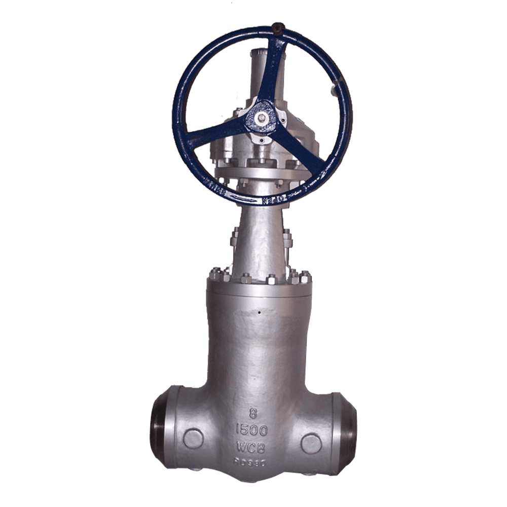
Pressure Seal Bonnet: Operating Principle
Conventional bolted-bonnet gate valves rely on a set of bolts to compress a gasket between the bonnet and the valve body. This arrangement is generally adequate at moderate temperatures and under stable pressure conditions. However, in main steam pipelines operating at Class 2500 and 600°C, frequent thermal cycling caused by load-following operation can create a serious sealing challenge.
The valve body and bonnet bolts expand at different rates, potentially resulting in a loss of bolt preload. As the gasket compression decreases, high-temperature steam may leak through the bonnet joint. Retightening can only be performed after shutdown and cooling, often requiring several hours and exposing maintenance personnel to burn hazards.
Pressure seal gate valves address this issue through a different sealing mechanism. Instead of relying primarily on bolting to compress the bonnet gasket, a metallic pressure seal ring is installed between the bonnet and the tapered sealing surface of the valve body. Internal pipeline pressure pushes the seal ring against the tapered surface from below. As pressure increases, the contact force increases, enhancing the seal through a self-energizing effect.
The bolts provide initial preload and positioning rather than carrying the entire internal pressure load. Consequently, bolt relaxation caused by thermal cycling is less likely to translate directly into external leakage at the bonnet joint.
Pressure Seal Integrity and Material Selection
The pressure seal mechanism requires careful handling and precise assembly. Scratches, deformation, or damage to the seal ring or tapered sealing surfaces can compromise the self-energizing effect and cause external leakage. All sealing components must therefore be kept clean and protected from impact during installation.
Bonnet and body materials must retain adequate strength and metallurgical stability at elevated temperatures. For main steam service, forged martensitic heat-resistant steels such as F91 are commonly specified.
These valves are often equipped with a rising stem, a flexible wedge gate, and Stellite hardfaced sealing surfaces. Butt-weld ends are commonly used in high-temperature, high-pressure pipelines to minimize external leakage points and accommodate demanding thermal stress conditions.
Gate valves are intended for fully open or fully closed service and should not be used for throttling. Each valve is designed in accordance with API 600 and tested in accordance with API 598.
Main steam and reheater steam lines in ultra-supercritical and supercritical power plants: The pressure seal bonnet is suited to demanding thermal cycling conditions.
High-temperature, high-pressure steam headers and bypass lines: Forged heat-resistant steel materials such as F91 provide the required high-temperature strength.
Power plant systems subject to frequent load cycling: The self-energizing bonnet seal reduces the risk of external leakage associated with bolt preload relaxation.
High-pressure service at Class 1500 and above: The sealing force increases with internal pressure, supporting reliable bonnet sealing under demanding operating conditions.
Critical service locations with limited maintenance windows: Reduced reliance on routine bonnet bolt retightening helps minimize maintenance requirements.
4. Selection Guidelines
Pressure Rating and Operating Conditions: Prioritize pressure seal bonnet valves for Class 1500 and above where high temperatures and frequent thermal cycling are expected. Bolted-bonnet designs may remain suitable for lower-pressure and moderate-temperature applications.
Body Material: Select F91 or another suitable martensitic heat-resistant steel for main steam and reheater steam service. For sour or corrosive media, select chromium-molybdenum steel or stainless steel according to the process conditions and applicable material requirements.
End Connections: Butt-weld ends are generally preferred for high-temperature, high-pressure service to reduce potential external leakage points and accommodate thermal stresses.
Sealing Surfaces: Specify Stellite hardfacing for applications involving significant erosion or frequent operation. Select the sealing materials and hardness combination according to the process medium and operating temperature.
Installation and Cleanliness: Thoroughly clean and inspect the pressure seal ring and tapered sealing surfaces before assembly. Scratches, dents, or contamination can compromise self-sealing performance.
Service Limitations: Gate valves are intended for on/off isolation only. For flow regulation, install a dedicated control valve or consider a globe valve where appropriate.
5. Project Case Study
Customer: FPLProject: Main Steam and Reheater Steam Systems at Turkey Point Power Plant, Turkey
The project involved main steam and reheater steam systems in an ultra-supercritical power generation unit operating at Class 2500 and 600°C. The original bolted-bonnet gate valves experienced bolt preload relaxation and external high-temperature steam leakage under frequent thermal cycling caused by load-following operation. Each shutdown for bolt retightening required approximately 8 hours and introduced a risk of burn injuries to maintenance personnel.
Flowork supplied 14 NPS 8–16, Class 2500 pressure seal gate valves featuring A182 F91 forged martensitic heat-resistant steel bodies, pressure-assisted self-sealing bonnets, rising-stem flexible wedge gates, Stellite 6 hardfaced sealing surfaces, and butt-weld ends.
The valves were designed in accordance with ASME B16.34 and underwent shell and sealing tests in accordance with API 598, witnessed on site by the FPL project quality control department.
Since commissioning in April 2022, the valves have operated continuously for 3 years without bonnet leakage. Shutdowns for bolt retightening have been eliminated, reducing the associated maintenance time from 8 hours per occurrence to zero. Annual unit availability has increased to 99.2%.
6. Frequently Asked Questions (FAQs)
Q1: Do pressure seal bonnets require bolt retightening at high temperatures?
Generally, no. The pressure seal design relies on internal pressure to enhance sealing, while the bolts primarily provide initial preload and positioning. If external leakage occurs, the valve should be addressed after shutdown and cooling in accordance with the approved maintenance procedure. Never attempt to tighten bonnet bolts under pressure.
Q2: What happens if the pressure seal ring or tapered sealing surface is scratched?
Damage can compromise the self-energizing sealing effect and result in external leakage. Keep all sealing components clean and protected during installation. Replace a damaged seal ring and inspect the mating surfaces before reassembly.
Q3: Can this valve be used to regulate steam flow?
No. Gate valves are intended for fully open or fully closed service. Operating a gate valve partially open can expose the sealing surfaces to high-velocity steam erosion. A dedicated control valve should be used for flow regulation.
Q4: What should I do if slight steam leakage occurs around the bonnet during operation?
Record and monitor the leakage while arranging an appropriate shutdown for inspection and repair. Do not attempt to tighten bonnet bolts under pressure, as this creates a risk of severe burns and potential valve failure.
Class1500 Pressure Seal Gate Valve

| NPS | in | 2 | 2 1/2 | 3 | 4 | 5 | 6 | 8 | 10 | 12 | 14 | 16 |
| d | mm | 47 | 57 | 70 | 92 | 111 | 136 | 178 | 222 | 263 | 289 | 330 |
| L(RF) | mm | 368 | 419 | 470 | 546 | 673 | 705 | 832 | 991 | 1130 | 1257 | 1384 |
| L(BW) | mm | 368 | 419 | 470 | 546 | 673 | 705 | 832 | 991 | 1130 | 1257 | 1384 |
| L(RTJ) | mm | 371 | 422 | 473 | 549 | 676 | 711 | 841 | 1000 | 1146 | 1276 | 1407 |
| d1 | mm | 92 | 105 | 127 | 157 | 186 | 216 | 270 | 324 | 381 | 413 | 470 |
| d2 | mm | 165 | 190.5 | 203.2 | 241.3 | 292.1 | 317.5 | 393.7 | 482.6 | 571.5 | 635 | 704.8 |
| D | mm | 216 | 244 | 267 | 311 | 375 | 394 | 483 | 585 | 675 | 750 | 825 |
| b | mm | 38.5 | 41.5 | 48 | 54 | 73.5 | 83 | 92.9 | 108 | 124 | 133.5 | 146.5 |
| n-Фd | mm | 8-26 | 8-29 | 8-32 | 8-35 | 8-42 | 12-39 | 12-45 | 12-51 | 16-54 | 16-61 | 16-67 |
| H | mm | 510 | 560 | 620 | 728 | 870 | 1000 | 1130 | 1360 | |||
| H1 | mm | 670 | 770 | 920 | 1070 | 1180 | 1410 | 1620 | 2020 | 2180 | ||
| W | mm | 280 | 300 | 350 | 400 | 450 | 500 | 750 | 900 | |||
| W1 | mm | 310 | 310 | 310 | 460 | 460 | 600 | 600 | 600 | 600 |
Class2500 Pressure Seal Gate Valve

| NPS | in | 2 | 2 1/2 | 3 | 4 | 5 | 6 | 8 | 10 | 12 |
| d | mm | 38 | 47 | 57 | 73 | 92 | 111 | 146 | 184 | 219 |
| L(RF) | mm | 451 | 508 | 578 | 673 | 794 | 914 | 1022 | 1270 | 1422 |
| L(BW) | mm | 451 | 508 | 578 | 673 | 794 | 914 | 1022 | 1270 | 1422 |
| L(RTJ) | mm | 454 | 514 | 584 | 683 | 807 | 927 | 1038 | 1292 | 1445 |
| d1 | mm | 92 | 105 | 127 | 157 | 186 | 216 | 270 | 324 | 381 |
| d2 | mm | 171.4 | 196.8 | 228.6 | 273 | 323.8 | 368.3 | 438.1 | 539.7 | 619.1 |
| D | mm | 235 | 267 | 305 | 356 | 419 | 483 | 550 | 675 | 760 |
| b | mm | 51 | 57.5 | 67 | 76.5 | 92.5 | 108 | 127 | 165.5 | 184.5 |
| n-Фd | mm | 8-29 | 8-32 | 8-35 | 8-42 | 8-48 | 8-54 | 12-54 | 12-67 | 12-74 |
| H | mm | 530 | 580 | 650 | 750 | 900 | 1040 | 1150 | 1400 | |
| H1 | mm | 580 | 630 | 700 | 800 | 960 | 1100 | 1200 | 1460 | 1660 |
| W | mm | 280 | 300 | 350 | 400 | 500 | 600 | 750 | 900 | |
| W1 | mm | 310 | 310 | 310 | 310 | 460 | 460 | 460 | 600 | 600 |
API Trim NO. Table
|
No |
Seat |
Gate、disc 、ball or body |
Stem |
No |
Seat |
Gate、disc 、ball or body |
Stem | |
| 01 | 13Cr | 13Cr | 13Cr | 31 | STELLITE | 321SS | 321SS | |
| 02 | 304SS | 304SS | 304SS | 32 | STELLITE | STELLITE | 321SS | |
| 03 | 310SS | 310SS | 310SS | 33 | 347SS | 347SS | 347SS | |
| 04 | HARD 13Cr | HARD 13Cr | 13Cr | 34 | STELLITE | 347SS | 347SS | |
| 05 | STELLITE | STELLITE | 13Cr | 35 | NICKEL ALLOY | 13Cr | 13Cr | |
| 06 | Cu-Ni | 13Cr | 13Cr | 36 | A105/PTFE | A105+ENP | A105+ENP | |
| 07 | 13Cr | HARD 13Cr | 13Cr | 37 | A105/PTFE | WCB+ENP | A105+ENP | |
| 08 | STELLITE | 13Cr | 13Cr | 38 | 13Cr/PTFE | 13Cr | 13Cr | |
| 09 | Cu-Ni | Cu-Ni | Cu-Ni | 39 | 304SS/PTFE | 304SS | 304SS | |
| 10 | 316SS | 316SS | 316SS | 40 | 316SS/PTFE | 316SS | 316SS | |
| 11 | Cu-Ni | STELLITE | Cu-Ni | 41 | A105/RPTFE | A105+ENP | A105+ENP | |
| 12 | STELLITE | 316SS | 316SS | 42 | A105/RPTFE | WCB+ENP | A105+ENP | |
| 13 | ALLOY 20 | ALLOY 20 | ALLOY 20 | 43 | 13Cr/RPTFE | 13Cr | 13Cr | |
| 14 | STELLITE | ALLOY 20 | ALLOY 20 | 44 | 304SS/RPTFE | 304SS | 304SS | |
| 15 | STELLITE | STELLITE | 304SS | 45 | 316SS/RPTFE | 316SS | 316SS | |
| 16 | STELLITE | STELLITE | 316SS | 46 | A105/NYLON | A105+ENP | A105+ENP | |
| 17 | STELLITE | STELLITE | 347SS | 47 | A105/NYLON | WCB+ENP | A105+ENP | |
| 18 | STELLITE | STELLITE | ALLOY 20 | 48 | A105/NYLON | 304SS | 304SS | |
| 19 | MONEL | MONEL | MONEL | 49 | A105/NYLON | 316SS | 316SS | |
| 20 | BRONZE | BRONZE | 13Cr | 50 | 13Cr/NYLON | 13Cr | 13Cr | |
| 21 | HASTELLOY B | HASTELLOY B | HASTELLOY B | 51 | 304SS/NYLON | 304SS | 304SS | |
| 22 |
| HASTELLOY C | HASTELLOY C | 52 | 316SS/NYLON | 316SS | 316SS | |
| 23 | STELLITE | 304SS | 304SS | 53 | A105/PEEK | A105+ENP | A105+ENP | |
| 24 | 304LSS | 304LSS | 304LSS | 54 | A105/PEEK | WCB+ENP | A105+ENP | |
| 25 | STELLITE | 304LSS | 304LSS | 55 | 13Cr/PEEK | 13Cr | 13Cr | |
| 26 | STELLITE | STELLITE | 304LSS | 56 | 304SS/PEEK | 304SS | 304SS | |
| 27 | 316LSS | 316LSS | 316LSS | 57 | 316SS/PEEK | 316SS | 316SS | |
| 28 | STELLITE | 316LSS | 316LSS |
|
|
|
|
|
| 29 | STELLITE | STELLITE | 316LSS |
|
|
| ||
| 30 | 321SS | 321SS | 321SS |
|
|
|
| |
Note:please indicate it directly in the
order for the internal part’smaterial uncovered in the table



 Optimized by Seraphinite Accelerator