



 Skip to content


LDAR monitoring data from oil refineries and chemical plants show that fugitive emissions from globe valves on process pipelines are approximately 3–5 times those from gate valves of the same diameter—not because of poor sealing, but due to their inherently different modes of operation. The stem of a gate valve rotates and moves up and down, spending most of its time in the fully open or fully closed positions; In contrast, the stem of a globe valve moves in a purely linear motion; when throttling, it remains at an intermediate opening position for extended periods, and each fine adjustment of the stem generates axial friction against the packing. This causes rapid localized wear and uneven pressure distribution in the packing rings, with micro-leaks often originating at these worn areas.
Low-emission globe valves address this issue through a three-layer structure: The first layer consists of a low-friction packing assembly—woven graphite reinforced with Inconel wires and compacted in layers—which reduces the valve stem’s coefficient of friction; the second layer features a disc spring that applies continuous load, automatically compensating for compression force as the packing wears, eliminating the need for manual periodic retightening of bolts; The third layer features an optional metal bellows seal, which expands and contracts with the valve stem, completely isolating the medium from the packing to achieve zero leakage. The upper seal features a metal conical structure; when the valve is fully open, the conical surface of the valve stem contacts the seal seat on the bonnet, completely depressurizing the packing area and allowing for in-service packing replacement under pressure.
1. Bypass lines for steam mainline pressure-reducing stations and control valves: Due to frequent fine adjustments of the valve stems and significant temperature fluctuations, these are the locations with the highest leak detection rates in LDAR inspections.
2. Sampling, vent, and condensate drain valves in refining hydrogenation units: These handle hydrogen-containing media and are operated frequently; a low-emission design can prevent the risk of hydrogen leakage.
3. Cryogenic process shut-off valves in LNG plants: Equipped with extended valve bonnets and cryogenic packing to prevent leaks caused by packing embrittlement under cryogenic conditions.
4. Pipelines carrying toxic media (chlorine, ammonia, phosgene): Bellows seals are used to achieve zero emissions and protect operator safety.
1) Step 1 – Choose the ISO 15848-1 endurance class by operating frequency. A valve used for isolation only, opened fewer than 100 times a year, is met by CO1 (205 cycles). Routine process isolation at 100-1,000 operations a year takes CO2 (10,000 cycles), and control-valve bypasses or any frequent throttling must have CO3 (100,000 cycles), or the packing will fail within one to two years.
2) Step 2 – Choose the sealing arrangement by toxicity and regulation. Ordinary hydrocarbons, steam and gas reach ISO 15848-1 Class B with the live-loaded packing set, which meets general LDAR requirements. For lethal media, strict TA Luft regimes or hydrogen, specify a metal bellows seal to reach Class A zero leakage, and insist on a backup packing set above the bellows so a bellows rupture cannot become an uncontrolled release.
3) Step 3 – Pick the body by temperature and medium. WCB for oil, water and steam from -29 to 425 °C; WC6 or WC9 chrome-moly for hot steam and hydrogen; CF8/CF8M for mildly corrosive streams; LCB/LCC for low temperature; 4A/5A duplex for chlorides; and Monel or Alloy 20 for strong acids and hydrofluoric acid.
4) Step 4 – Set ends and trim. RF or RTJ flanged ends where the valve is serviced in line, butt weld ends where it is not, and trim to Trim 01 (13Cr), Trim 05 (Stellite 6, for hot erosive duty) or Trim 10 (all 316).
Options: API 607 fire-safe, NACE MR0175 sour service, EN 10204 3.1/3.2 certification, gear or electric operation, extended cryogenic bonnet, and locking devices.
For MISC Berhad’s LNG carrier fleet in Malaysia, including Moss-type and Mark III membrane LNG vessels, conventional brass globe valves installed in seawater cooling and ballast systems suffered from galvanic corrosion and stem degradation. Flowork supplied NPS 1/2–2, Class 150 bronze globe valves featuring ASTM B148 C95800 nickel aluminum bronze bodies, 410 stainless steel stems, sacrificial aluminum bronze nuts for galvanic protection, and replaceable PTFE seats. The valves were certified by DNV and tested according to API 598 requirements. Since delivery in 2022, the valves have operated globally for three years without stem corrosion failures, extending MTBF from 11 months to more than five years.
Q 1: Why are globe valves more prone to leakage than gate valves of the same diameter?
A: Because of the different valve stem motion patterns. The gate valve stem rotates and moves up and down, spending most of its time in the fully open or fully closed positions; the globe valve stem performs purely linear reciprocating motion. During throttling, it remains at a mid-open position for extended periods, and each stem movement generates axial friction against the packing. The packing wears out 3–5 times faster than in gate valves, resulting in a higher probability of micro-seepage. Therefore, globe valves require more stringent low-emission design specifications.
Q 2: What is the purpose of disc spring loading?
A: Packing gradually loosens under temperature cycling and prolonged friction; a decrease in clamping force leads to leakage. Conventional globe valves require manual tightening of the packing gland bolts at regular intervals; disc springs automatically compensate for clamping force after packing wear, maintaining stable sealing pressure. This eliminates the need for manual retightening for several years, significantly reducing LDAR maintenance workload.
Q 3: When should a bellows-sealed globe valve be selected?
Answer: For highly toxic media (chlorine, ammonia, phosgene), hydrogen-containing media, and applications subject to strict EU TA Luft regulations, a metal bellows seal is recommended. The bellows, constructed of stainless steel or Inconel in a thin-walled welded structure, expand and contract with the valve stem, completely isolating the medium from the packing. This design achieves ISO 15848-1 Class A zero emissions; a layer of backup packing must be installed around the outer surface of the bellows to prevent sudden leaks in the event of bellows rupture.
Q 4: Can the packing in a low-emission globe valve be replaced online?
A: Yes. When the valve is fully open, the conical surface of the valve stem fits tightly against the upper seal seat, cutting off the flow of the medium to the packing chamber. At this point, the packing gland can be loosened to replace the packing without the need to depressurize the pipeline or shut down the system. The upper seal is a standard feature of low-emission globe valves; please note that packing should not be replaced when the valve is in a half-open position.
Class150
Low Emission Globe valve

| NPS | in | 2 | 2 1/2 | 3 | 4 | 5 | 6 | 8 | 10 | 12 |
| d | mm | 51 | 64 | 76 | 102 | 127 | 152 | 203 | 254 | 305 |
| L(RF) | mm | 203 | 216 | 241 | 292 | 356 | 406 | 495 | 622 | 698 |
| L(BW) | mm | 203 | 216 | 241 | 292 | 356 | 406 | 495 | 622 | 698 |
| L(RTJ) | mm | 216 | 229 | 254 | 305 | 369 | 419 | 508 | 635 | 711 |
| d1 | mm | 92 | 105 | 127 | 157 | 186 | 216 | 270 | 324 | 381 |
| d2 | mm | 120.5 | 139.5 | 152.5 | 190.5 | 216 | 241.5 | 298.5 | 362 | 432 |
| D | mm | 152 | 178 | 190 | 229 | 254 | 279 | 343 | 406 | 483 |
| b | mm | 16 | 18 | 19 | 24 | 24 | 26 | 29 | 31 | 32 |
| n-Фd | mm | 4-19 | 4-19 | 4-19 | 8-19 | 8-22 | 8-22 | 8-22 | 12-25 | 12-25 |
| H | mm | 330 | 360 | 390 | 445 | 480 | 520 | 600 | 773 | 880 |
| H1 | mm |
|
|
|
|
| 556 | 658 | 805 | 955 |
| W | mm | 200 | 200 | 250 | 300 | 350 | 350 | 500 | 500 | 550 |
| W1 | mm |
|
|
|
|
| 310 | 310 | 460 | 460 |
Class300
Low Emission Globe valve
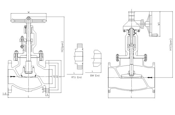
| NPS | in | 2 | 2 1/2 | 3 | 4 | 5 | 6 | 8 | 10 | 12 |
| d | mm | 51 | 64 | 76 | 102 | 127 | 152 | 203 | 254 | 305 |
| L(RF) | mm | 267 | 292 | 318 | 356 | 400 | 444 | 559 | 622 | 711 |
| L(BW) | mm | 267 | 292 | 318 | 356 | 400 | 444 | 559 | 622 | 711 |
| L(RTJ) | mm | 283 | 308 | 333 | 371 | 416 | 460 | 575 | 638 | 727 |
| d1 | mm | 92 | 105 | 127 | 157 | 186 | 216 | 270 | 324 | 381 |
| d2 | mm | 127 | 149 | 168.5 | 200 | 235 | 270 | 330 | 387.5 | 451 |
| D | mm | 165 | 190 | 210 | 254 | 279 | 318 | 381 | 445 | 521 |
| b | mm | 23 | 26 | 29 | 32 | 35 | 37 | 42 | 48 | 51 |
| n-Фd | mm | 8-19 | 8-22 | 8-22 | 8-22 | 8-22 | 12-22 | 12-25 | 16-29 | 16-32 |
| H | mm | 385 | 420 | 440 | 515 | 580 | 660 | 900 | 950 | 1030 |
| H1 | mm |
|
|
|
|
| 690 | 950 | 990 | 1080 |
| W | mm | 250 | 250 | 300 | 350 | 450 | 500 | 500 | 550 | 550 |
| W1 | mm |
|
|
|
|
| 310 | 460 | 460 | 460 |
Class600
Low Emission Globe valve
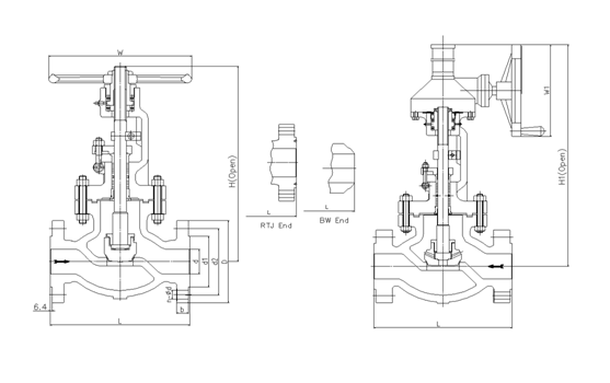
| NPS | in | 2 | 2 1/2 | 3 | 4 | 5 | 6 | 8 | 10 | 12 |
| d | mm | 51 | 64 | 76 | 102 | 127 | 152 | 200 | 248 | 298 |
| L(RF) | mm | 292 | 330 | 356 | 432 | 508 | 559 | 660 | 787 | 838 |
| L(BW) | mm | 292 | 330 | 356 | 432 | 508 | 559 | 660 | 787 | 838 |
| L(RTJ) | mm | 295 | 333 | 359 | 435 | 511 | 562 | 664 | 791 | 841 |
| d1 | mm | 92 | 105 | 127 | 157 | 186 | 216 | 270 | 324 | 381 |
| d2 | mm | 127 | 149 | 168.5 | 216 | 267 | 292 | 349 | 432 | 489 |
| D | mm | 165 | 190 | 210 | 273 | 330 | 356 | 419 | 508 | 559 |
| b | mm | 26 | 29 | 32 | 38 | 45 | 48 | 56 | 64 | 67 |
| n-Фd | mm | 8-19 | 8-22 | 8-22 | 8-25 | 8-29 | 12-29 | 12-32 | 16-35 | 20-35 |
| H | mm | 360 | 410 | 465 | 545 | 625 | 785 | 930 |
|
|
| H1 | mm |
|
|
| 575 | 660 | 820 | 960 | 1040 | 1280 |
| W | mm | 250 | 300 | 350 | 400 | 500 | 550 | 650 |
|
|
| W1 | mm |
|
|
| 310 | 310 | 460 | 460 | 610 | 610 |
Class900
Low Emission Globe valve
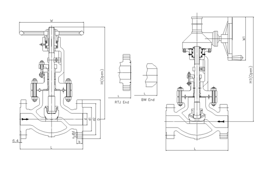
| NPS | in | 2 | 2 1/2 | 3 | 4 | 5 | 6 | 8 | 10 |
| d | mm | 47 | 57 | 73 | 98 | 121 | 146 | 190 | 234 |
| L(RF) | mm | 368 | 419 | 381 | 457 | 559 | 610 | 737 | 838 |
| L(BW) | mm | 368 | 419 | 381 | 457 | 559 | 610 | 737 | 838 |
| L(RTJ) | mm | 371 | 422 | 384 | 460 | 562 | 613 | 740 | 841 |
| d1 | mm | 92 | 105 | 127 | 157 | 186 | 216 | 270 | 324 |
| d2 | mm | 165 | 190.5 | 190.5 | 235 | 279.4 | 317.5 | 393.7 | 469.9 |
| D | mm | 216 | 244 | 241 | 292 | 349 | 381 | 470 | 545 |
| b | mm | 38.5 | 41.5 | 38.5 | 44.5 | 51 | 56 | 64 | 70 |
| n-Фd | mm | 8-26 | 8-29 | 8-26 | 8-32 | 8-35 | 12-32 | 12-39 | 16-39 |
| H | mm | 480 | 520 | 564 | 685 | 780 | 950 |
|
|
| H1 | mm |
|
| 630 | 720 | 840 | 1015 | 1100 | 1185 |
| W | mm | 350 | 350 | 400 | 450 | 550 | 650 |
|
|
| W1 | mm |
|
| 310 | 310 | 460 | 460 | 610 | 610 |
Class1500
Low Emission Globe valve
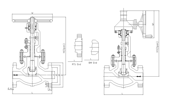
| NPS | in | 2 | 2 1/2 | 3 | 4 | 5 | 6 | 8 |
| d | mm | 47 | 57 | 70 | 92 | 111 | 136 | 178 |
| L(RF) | mm | 368 | 419 | 470 | 546 | 673 | 705 | 832 |
| L(BW) | mm | 368 | 419 | 470 | 546 | 673 | 705 | 832 |
| L(RTJ) | mm | 371 | 422 | 473 | 549 | 676 | 711 | 841 |
| d1 | mm | 92 | 105 | 127 | 157 | 186 | 216 | 270 |
| d2 | mm | 165 | 190.5 | 203.2 | 241.3 | 292.1 | 317.5 | 393.7 |
| D | mm | 216 | 244 | 267 | 311 | 375 | 394 | 483 |
| b | mm | 38.5 | 41.5 | 48 | 54 | 73.5 | 83 | 92.9 |
| n-Фd | mm | 8-26 | 8-29 | 8-32 | 8-35 | 8-42 | 12-39 | 12-45 |
| H | mm | 592 | 660 | 692 |
|
|
|
|
| H1 | mm |
|
|
| 907 | 950 | 1015 | 1145 |
| W | mm | 350 | 400 | 500 |
|
|
|
|
| W1 | mm |
|
|
| 460 | 610 | 610 | 610 |
API Trim NO.
Table
|
No |
Seat |
Gate、disc 、ball or body |
Stem |
No |
Seat |
Gate、disc 、ball or body |
Stem | |
| 01 | 13Cr | 13Cr | 13Cr | 31 | STELLITE | 321SS | 321SS | |
| 02 | 304SS | 304SS | 304SS | 32 | STELLITE | STELLITE | 321SS | |
| 03 | 310SS | 310SS | 310SS | 33 | 347SS | 347SS | 347SS | |
| 04 | HARD 13Cr | HARD 13Cr | 13Cr | 34 | STELLITE | 347SS | 347SS | |
| 05 | STELLITE | STELLITE | 13Cr | 35 | NICKEL ALLOY | 13Cr | 13Cr | |
| 06 | Cu-Ni | 13Cr | 13Cr | 36 | A105/PTFE | A105+ENP | A105+ENP | |
| 07 | 13Cr | HARD 13Cr | 13Cr | 37 | A105/PTFE | WCB+ENP | A105+ENP | |
| 08 | STELLITE | 13Cr | 13Cr | 38 | 13Cr/PTFE | 13Cr | 13Cr | |
| 09 | Cu-Ni | Cu-Ni | Cu-Ni | 39 | 304SS/PTFE | 304SS | 304SS | |
| 10 | 316SS | 316SS | 316SS | 40 | 316SS/PTFE | 316SS | 316SS | |
| 11 | Cu-Ni | STELLITE | Cu-Ni | 41 | A105/RPTFE | A105+ENP | A105+ENP | |
| 12 | STELLITE | 316SS | 316SS | 42 | A105/RPTFE | WCB+ENP | A105+ENP | |
| 13 | ALLOY 20 | ALLOY 20 | ALLOY 20 | 43 | 13Cr/RPTFE | 13Cr | 13Cr | |
| 14 | STELLITE | ALLOY 20 | ALLOY 20 | 44 | 304SS/RPTFE | 304SS | 304SS | |
| 15 | STELLITE | STELLITE | 304SS | 45 | 316SS/RPTFE | 316SS | 316SS | |
| 16 | STELLITE | STELLITE | 316SS | 46 | A105/NYLON | A105+ENP | A105+ENP | |
| 17 | STELLITE | STELLITE | 347SS | 47 | A105/NYLON | WCB+ENP | A105+ENP | |
| 18 | STELLITE | STELLITE | ALLOY 20 | 48 | A105/NYLON | 304SS | 304SS | |
| 19 | MONEL | MONEL | MONEL | 49 | A105/NYLON | 316SS | 316SS | |
| 20 | BRONZE | BRONZE | 13Cr | 50 | 13Cr/NYLON | 13Cr | 13Cr | |
| 21 | HASTELLOY B | HASTELLOY B | HASTELLOY B | 51 | 304SS/NYLON | 304SS | 304SS | |
| 22 |
| HASTELLOY C | HASTELLOY C | 52 | 316SS/NYLON | 316SS | 316SS | |
| 23 | STELLITE | 304SS | 304SS | 53 | A105/PEEK | A105+ENP | A105+ENP | |
| 24 | 304LSS | 304LSS | 304LSS | 54 | A105/PEEK | WCB+ENP | A105+ENP | |
| 25 | STELLITE | 304LSS | 304LSS | 55 | 13Cr/PEEK | 13Cr | 13Cr | |
| 26 | STELLITE | STELLITE | 304LSS | 56 | 304SS/PEEK | 304SS | 304SS | |
| 27 | 316LSS | 316LSS | 316LSS | 57 | 316SS/PEEK | 316SS | 316SS | |
| 28 | STELLITE | 316LSS | 316LSS |
|
|
|
|
|
| 29 | STELLITE | STELLITE | 316LSS |
|
|
| ||
| 30 | 321SS | 321SS | 321SS |
|
|
|
| |
Note:please indicate it directly in the
order for the internal part’smaterial uncovered in the table


 Optimized by Seraphinite Accelerator