



 Skip to content

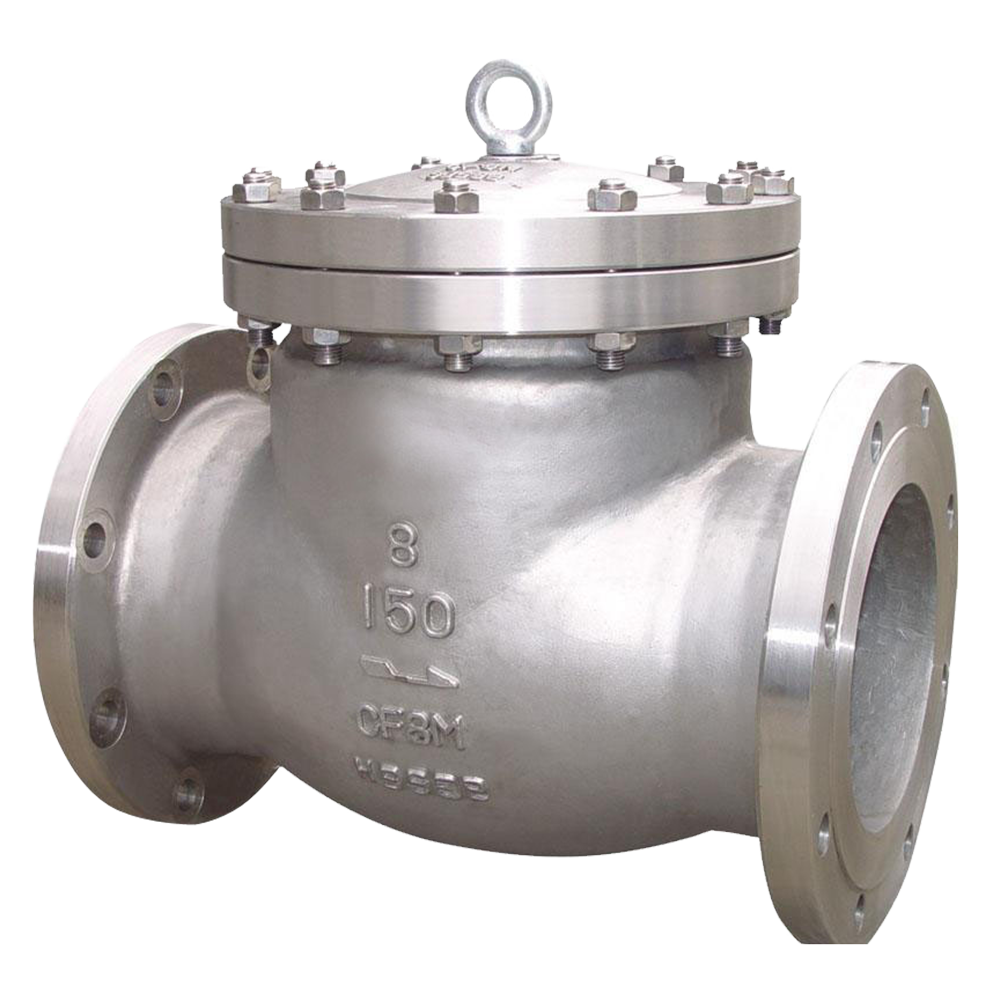
The first step in selecting a special alloy check valve is identifying which process media require nickel-based alloys. Sulfuric acid, phosphoric acid, mixed acids, and hydrofluoric acid can rapidly corrode 304 and 316 stainless steels, while duplex stainless steels may only slow the corrosion process. CN7M (Alloy 20) offers resistance to sulfuric and phosphoric acids, while Monel is commonly selected for hydrofluoric acid and seawater service. These properties are determined by the alloy's chemical composition and cannot be reliably compensated for by increasing wall thickness or applying a surface coating. Selecting the wrong alloy can result in pitting corrosion and through-wall penetration within months.
Check valves operate differently from other valve types. They have no handwheel or actuator and rely on the direction of fluid flow to open and close automatically. In a swing check valve, the disc pivots on a hinge pin near the top of the body. Forward flow pushes the disc open, while reverse flow causes it to return to the seat under gravity and reverse-pressure forces. Installed at pump and compressor discharge outlets, the valve prevents backflow and helps protect impellers, casings, and other equipment from reverse-flow damage.
Failure is often concentrated in the moving components. Prolonged exposure to corrosive media can wear or foul the hinge pin, preventing the disc from returning fully to its seat. If the disc remains stuck open, reverse flow can damage pump impellers and compressor casings, and the problem may not be immediately apparent during routine operation. Wet hydrogen sulfide service can also cause sulfide stress cracking in carbon steel and high-strength internal components. Materials must therefore comply with NACE MR0175, with hardness limited to 22 HRC where specified by the applicable material and service requirements. Each valve undergoes body and seat leakage testing in accordance with API 598 before shipment.
Sulfuric and phosphoric acid process lines: CN7M (Alloy 20) bodies provide corrosion resistance in suitable acid service.
Pump discharge lines in hydrofluoric acid alkylation units: Monel components offer resistance to hydrofluoric acid under appropriate operating conditions.
Wet H₂S oil and gas processing lines: Internal components must meet NACE MR0175 requirements, with hardness not exceeding 22 HRC where applicable.
Pump and compressor discharge lines handling highly corrosive media: Prevent reverse flow that could damage rotating equipment and pressure-containing components.
Seawater and chloride-containing cooling water lines: Monel can provide resistance to pitting and crevice corrosion, subject to the specific alloy grade and service conditions.
Material Selection: Choose CN7M (Alloy 20) for suitable sulfuric and phosphoric acid applications, and Monel for appropriate hydrofluoric acid and seawater services. For wet H₂S service, ensure the internal components comply with NACE MR0175 and meet the applicable hardness limit of 22 HRC.
Installation Orientation: Swing check valves are generally suitable for horizontal pipelines. For vertical pipelines with upward flow, select a lift check valve or another design specifically suitable for the installation orientation. Specify the pipeline flow direction when ordering.
Straight Pipe Runs and Flow Rate: Where practicable, provide 3–5 pipe diameters of straight pipe upstream of the valve at pump discharge outlets to help stabilize flow and reduce disc flutter under low-flow conditions. Confirm the actual installation requirements against the valve manufacturer's recommendations.
Inspection Intervals: For corrosive services, consider an initial inspection after six months of operation. Pay particular attention to hinge-pin wear, pitting on the sealing surfaces, and disc movement. Adjust subsequent inspection intervals according to the inspection findings and actual operating conditions.
Gulf Keystone Petroleum International Ltd., Iraq – Sour Crude Oil Processing and Export Pipeline
Gulf Keystone Petroleum International Ltd. in Iraq processes sour crude oil containing 2.5% sulfur. Its crude oil export and processing pipelines operate at Class 300 and 150°C and are exposed to high concentrations of H₂S. The originally installed carbon steel check valves suffered sulfide stress cracking in wet H₂S service within nine months, triggering repeated gas alarms and forcing the affected unit to be isolated.
Flowork supplied 52 special alloy check valves in sizes NPS 2–8, rated Class 300, featuring 316L stainless steel bodies, hardened internal components with a maximum hardness of 22 HRC in compliance with NACE MR0175, hydraulically damped swing discs, and Stellite 6 hardfaced sealing surfaces. The valves were designed in accordance with API 594 and underwent body and seat leakage testing in accordance with API 598, witnessed on site by Gulf Keystone's technical inspection department.
Since commissioning in October 2021, the valves have reportedly operated for four consecutive years without cracking or leakage. Gas alarm incidents have decreased from six per year to zero, and the export facilities have maintained 99% availability.
Q1: How can you tell if a check valve is stuck open when it has no handwheel or actuator?
If downstream pressure drops rapidly after the pump stops or the equipment begins to rotate backward, the disc may not be closing properly. Comparing pressure readings before and after shutdown can help identify a suspected backflow problem. Further inspection may be required to confirm the cause.
Q2: Why is internal component hardness restricted in wet H₂S service?
Higher hardness can increase susceptibility to sulfide stress cracking in susceptible materials. NACE MR0175 specifies material and hardness requirements for sour service, including a commonly applicable maximum hardness of 22 HRC for many materials. Always verify the exact requirements for the selected material and component.
Q3: Why does a check valve produce knocking or banging noises?
At low flow rates, the disc may flutter repeatedly instead of remaining stable. Pipeline start-up and shutdown can also generate water hammer or pressure surges. Check the actual flow rate and verify that the upstream straight-pipe run and valve sizing are appropriate.
Q4: How often should a check valve be inspected in corrosive service?
Consider an initial inspection after six months of operation. Focus on hinge-pin wear, pitting on the sealing surfaces, and the full travel of the disc. Adjust subsequent inspection intervals based on the findings, corrosion rate, and operating conditions.
Q5: Can a check valve be installed in a vertical pipeline?
Yes, but the valve design must suit the installation orientation and flow direction. Swing check valves rely partly on gravity to return the disc to its seat and are generally best suited to horizontal lines. For vertical pipelines with upward flow, use a lift check valve or a spring-assisted design specifically rated for that orientation.
Class150
Special Alloy check Valve
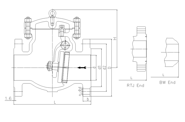
| NPS | in | 2 | 2 1/2 | 3 | 4 | 5 | 6 | 8 | 10 | 12 | 14 | 16 | 18 | 20 | 24 |
| d | mm | 51 | 64 | 76 | 102 | 127 | 152 | 203 | 254 | 305 | 337 | 387 | 438 | 489 | 591 |
| L(RF) | mm | 203 | 216 | 241 | 292 | 330 | 356 | 495 | 622 | 699 | 787 | 864 | 978 | 978 | 1295 |
| L(BW) | mm | 203 | 216 | 241 | 292 | 330 | 356 | 495 | 622 | 699 | 787 | 864 | 978 | 978 | 1295 |
| L(RTJ) | mm | 216 | 229 | 254 | 305 | 343 | 368 | 508 | 635 | 711 | 800 | 876 | 991 | 991 | 1308 |
| d1 | mm | 92 | 105 | 127 | 157 | 186 | 216 | 270 | 324 | 381 | 413 | 470 | 533 | 584 | 692 |
| d2 | mm | 120.5 | 139.5 | 152.5 | 190.5 | 216 | 241.5 | 298.5 | 362 | 432 | 476 | 540 | 578 | 635 | 749.5 |
| D | mm | 152 | 178 | 190 | 229 | 254 | 279 | 343 | 406 | 483 | 533 | 597 | 635 | 699 | 813 |
| b | mm | 16 | 18 | 19 | 24 | 24 | 26 | 29 | 31 | 32 | 35 | 37 | 40 | 43 | 48 |
| n-Фd | mm | 4-19 | 4-19 | 4-19 | 8-19 | 8-22 | 8-22 | 8-22 | 12-25 | 12-25 | 12-29 | 16-29 | 16-32 | 20-32 | 20-35 |
| H | mm | 132 | 147 | 176 | 198 | 255 | 320 | 380 | 440 | 480 | 530 | 580 | 618 | 657 | 760 |
Class300
Special Alloy check Valve
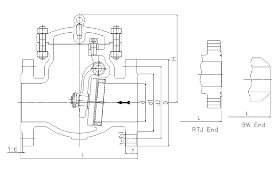
| NPS | in | 2 | 2 1/2 | 3 | 4 | 5 | 6 | 8 | 10 | 12 | 14 | 16 | 18 | 20 | 24 |
| d | mm | 51 | 64 | 76 | 102 | 127 | 152 | 203 | 254 | 305 | 337 | 387 | 432 | 483 | 584 |
| L(RF) | mm | 267 | 292 | 318 | 356 | 400 | 445 | 533 | 622 | 711 | 838 | 864 | 978 | 1016 | 1346 |
| L(BW) | mm | 267 | 292 | 318 | 356 | 400 | 445 | 533 | 622 | 711 | 838 | 864 | 978 | 1016 | 1346 |
| L(RTJ) | mm | 283 | 308 | 333 | 371 | 416 | 460 | 549 | 638 | 727 | 854 | 879 | 994 | 1035 | 1368 |
| d1 | mm | 92 | 105 | 127 | 157 | 186 | 216 | 270 | 324 | 381 | 413 | 470 | 533 | 584 | 692 |
| d2 | mm | 127 | 149 | 168.5 | 200 | 235 | 270 | 330 | 387.5 | 451 | 514.5 | 571.5 | 628.5 | 686 | 813 |
| D | mm | 165 | 190 | 210 | 254 | 279 | 318 | 381 | 445 | 521 | 584 | 648 | 711 | 775 | 914 |
| b | mm | 23 | 26 | 29 | 32 | 35 | 37 | 42 | 48 | 51 | 54 | 58 | 61 | 64 | 70 |
| n-Фd | mm | 8-19 | 8-22 | 8-22 | 8-22 | 8-22 | 12-22 | 12-25 | 16-29 | 16-32 | 20-32 | 20-35 | 24-35 | 24-35 | 24-41 |
| H | mm | 144 | 149 | 210 | 260 | 295 | 326 | 380 | 440 | 520 | 540 | 588 | 670 | 720 | 850 |
Class600
Special Alloy check Valve
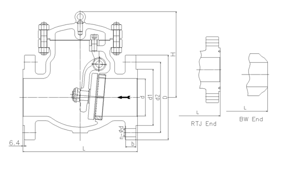
| NPS | in | 2 | 2 1/2 | 3 | 4 | 5 | 6 | 8 | 10 | 12 | 14 | 16 | 18 | 20 | 24 |
| d | mm | 51 | 64 | 76 | 102 | 127 | 152 | 200 | 248 | 298 | 327 | 375 | 419 | 464 | 559 |
| L(RF) | mm | 292 | 330 | 356 | 432 | 508 | 559 | 660 | 787 | 838 | 889 | 991 | 1092 | 1194 | 1397 |
| L(BW) | mm | 292 | 330 | 356 | 432 | 508 | 559 | 660 | 787 | 838 | 889 | 991 | 1092 | 1194 | 1397 |
| L(RTJ) | mm | 295 | 333 | 359 | 435 | 511 | 562 | 664 | 791 | 841 | 892 | 994 | 1095 | 1200 | 1407 |
| d1 | mm | 92 | 105 | 127 | 157 | 186 | 216 | 270 | 324 | 381 | 413 | 470 | 533 | 584 | 692 |
| d2 | mm | 127 | 149 | 168.5 | 216 | 267 | 292 | 349 | 432 | 489 | 527 | 603 | 654 | 724 | 838 |
| D | mm | 165 | 190 | 210 | 273 | 330 | 356 | 419 | 508 | 559 | 603 | 686 | 743 | 813 | 940 |
| b | mm | 26 | 29 | 32 | 38 | 45 | 48 | 56 | 64 | 67 | 70 | 77 | 83 | 89 | 102 |
| n-Фd | mm | 8-19 | 8-22 | 8-22 | 8-25 | 8-29 | 12-29 | 12-32 | 16-35 | 20-35 | 20-38 | 20-41 | 20-44 | 24-44 | 24-52 |
| H | mm | 170 | 178 | 246 | 290 | 320 | 360 | 430 | 502 | 554 | 595 | 680 | 778 | 970 | 1100 |
Class900
Special Alloy check Valve
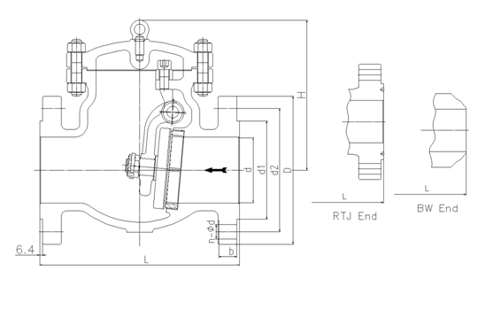
| NPS | in | 2 | 2 1/2 | 3 | 4 | 5 | 6 | 8 | 10 | 12 | 14 | 16 | 18 | 20 | 24 |
| d | mm | 47 | 57 | 73 | 98 | 121 | 146 | 190 | 234 | 282 | 311 | 354 | 400 | 444 | 533 |
| L(RF) | mm | 368 | 419 | 381 | 457 | 559 | 610 | 737 | 838 | 965 | 1029 | 1130 | 1219 | 1321 | 1549 |
| L(BW) | mm | 368 | 419 | 381 | 457 | 559 | 610 | 737 | 838 | 965 | 1029 | 1130 | 1219 | 1321 | 1549 |
| L(RTJ) | mm | 371 | 422 | 384 | 460 | 562 | 613 | 740 | 841 | 968 | 1038 | 1140 | 1232 | 1334 | 1568 |
| d1 | mm | 92 | 105 | 127 | 157 | 186 | 216 | 270 | 324 | 381 | 413 | 470 | 533 | 584 | 692 |
| d2 | mm | 165 | 190.5 | 190.5 | 235 | 279.4 | 317.5 | 393.7 | 469.9 | 533.4 | 558.8 | 615.9 | 685.8 | 749.3 | 901.7 |
| D | mm | 216 | 244 | 241 | 292 | 349 | 381 | 470 | 545 | 610 | 640 | 705 | 785 | 855 | 1040 |
| b | mm | 38.5 | 41.5 | 38.5 | 44.5 | 51 | 56 | 64 | 70 | 79.5 | 86 | 89 | 102 | 108 | 140 |
| n-Фd | mm | 8-26 | 8-29 | 8-26 | 8-32 | 8-35 | 12-32 | 12-39 | 16-39 | 20-39 | 20-42 | 20-45 | 20-51 | 20-54 | 20-67 |
| H | mm | 200 | 220 | 280 | 320 | 360 | 400 | 480 | 560 | 630 | 680 | 780 | 880 | 1050 | 1200 |
Class1500
Special Alloy check Valve
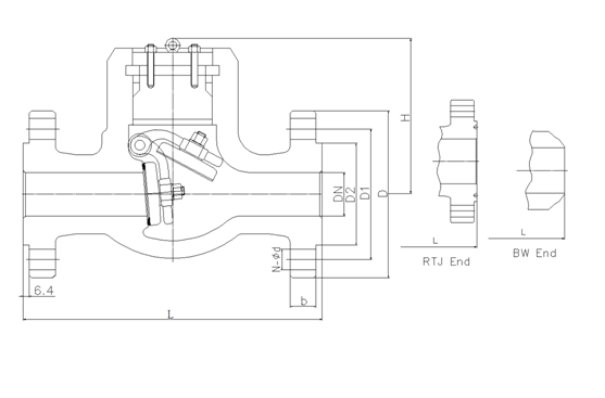
| NPS | in | 2 | 2 1/2 | 3 | 4 | 5 | 6 | 8 | 10 | 12 | 14 | 16 |
| d | mm | 47 | 57 | 70 | 92 | 111 | 136 | 178 | 222 | 263 | 289 | 330 |
| L(RF) | mm | 368 | 419 | 470 | 546 | 673 | 705 | 832 | 991 | 1130 | 1257 | 1384 |
| L(BW) | mm | 368 | 419 | 470 | 546 | 673 | 705 | 832 | 991 | 1130 | 1257 | 1384 |
| L(RTJ) | mm | 371 | 422 | 473 | 549 | 676 | 711 | 841 | 1000 | 1146 | 1276 | 1407 |
| d1 | mm | 92 | 105 | 127 | 157 | 186 | 216 | 270 | 324 | 381 | 413 | 470 |
| d2 | mm | 165 | 190.5 | 203.2 | 241.3 | 292.1 | 317.5 | 393.7 | 482.6 | 571.5 | 635 | 704.8 |
| D | mm | 216 | 244 | 267 | 311 | 375 | 394 | 483 | 585 | 675 | 750 | 825 |
| b | mm | 38.5 | 41.5 | 48 | 54 | 73.5 | 83 | 92.9 | 108 | 124 | 133.5 | 146.5 |
| n-Фd | mm | 8-26 | 8-29 | 8-32 | 8-35 | 8-42 | 12-39 | 12-45 | 12-51 | 16-54 | 16-61 | 16-67 |
| H | mm | 210 | 240 | 303 | 340 | 380 | 430 | 500 | 590 | 660 | 710 | 820 |
Class2500
Special Alloy check Valve
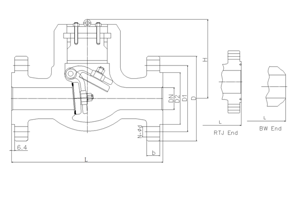
| NPS | in | 2 | 2 1/2 | 3 | 4 | 5 | 6 | 8 | 10 | 12 |
| d | mm | 38 | 47 | 57 | 73 | 92 | 111 | 146 | 184 | 219 |
| L(RF) | mm | 451 | 508 | 578 | 673 | 794 | 914 | 1022 | 1270 | 1422 |
| L(BW) | mm | 451 | 508 | 578 | 673 | 794 | 914 | 1022 | 1270 | 1422 |
| L(RTJ) | mm | 454 | 514 | 584 | 683 | 807 | 927 | 1038 | 1292 | 1445 |
| d1 | mm | 92 | 105 | 127 | 157 | 186 | 216 | 270 | 324 | 381 |
| d2 | mm | 171.4 | 196.8 | 228.6 | 273 | 323.8 | 368.3 | 438.1 | 539.7 | 619.1 |
| D | mm | 235 | 267 | 305 | 356 | 419 | 483 | 550 | 675 | 760 |
| b | mm | 51 | 57.5 | 67 | 76.5 | 92.5 | 108 | 127 | 165.5 | 184.5 |
| n-Фd | mm | 8-29 | 8-32 | 8-35 | 8-42 | 8-48 | 8-54 | 12-54 | 12-67 | 12-74 |
| H | mm | 230 | 260 | 330 | 370 | 410 | 460 | 530 | 620 | 690 |
API Trim NO.
Table
|
No |
Seat |
Gate、disc 、ball or body |
Stem |
No |
Seat |
Gate、disc 、ball or body |
Stem | |
| 01 | 13Cr | 13Cr | 13Cr | 31 | STELLITE | 321SS | 321SS | |
| 02 | 304SS | 304SS | 304SS | 32 | STELLITE | STELLITE | 321SS | |
| 03 | 310SS | 310SS | 310SS | 33 | 347SS | 347SS | 347SS | |
| 04 | HARD 13Cr | HARD 13Cr | 13Cr | 34 | STELLITE | 347SS | 347SS | |
| 05 | STELLITE | STELLITE | 13Cr | 35 | NICKEL ALLOY | 13Cr | 13Cr | |
| 06 | Cu-Ni | 13Cr | 13Cr | 36 | A105/PTFE | A105+ENP | A105+ENP | |
| 07 | 13Cr | HARD 13Cr | 13Cr | 37 | A105/PTFE | WCB+ENP | A105+ENP | |
| 08 | STELLITE | 13Cr | 13Cr | 38 | 13Cr/PTFE | 13Cr | 13Cr | |
| 09 | Cu-Ni | Cu-Ni | Cu-Ni | 39 | 304SS/PTFE | 304SS | 304SS | |
| 10 | 316SS | 316SS | 316SS | 40 | 316SS/PTFE | 316SS | 316SS | |
| 11 | Cu-Ni | STELLITE | Cu-Ni | 41 | A105/RPTFE | A105+ENP | A105+ENP | |
| 12 | STELLITE | 316SS | 316SS | 42 | A105/RPTFE | WCB+ENP | A105+ENP | |
| 13 | ALLOY 20 | ALLOY 20 | ALLOY 20 | 43 | 13Cr/RPTFE | 13Cr | 13Cr | |
| 14 | STELLITE | ALLOY 20 | ALLOY 20 | 44 | 304SS/RPTFE | 304SS | 304SS | |
| 15 | STELLITE | STELLITE | 304SS | 45 | 316SS/RPTFE | 316SS | 316SS | |
| 16 | STELLITE | STELLITE | 316SS | 46 | A105/NYLON | A105+ENP | A105+ENP | |
| 17 | STELLITE | STELLITE | 347SS | 47 | A105/NYLON | WCB+ENP | A105+ENP | |
| 18 | STELLITE | STELLITE | ALLOY 20 | 48 | A105/NYLON | 304SS | 304SS | |
| 19 | MONEL | MONEL | MONEL | 49 | A105/NYLON | 316SS | 316SS | |
| 20 | BRONZE | BRONZE | 13Cr | 50 | 13Cr/NYLON | 13Cr | 13Cr | |
| 21 | HASTELLOY B | HASTELLOY B | HASTELLOY B | 51 | 304SS/NYLON | 304SS | 304SS | |
| 22 |
| HASTELLOY C | HASTELLOY C | 52 | 316SS/NYLON | 316SS | 316SS | |
| 23 | STELLITE | 304SS | 304SS | 53 | A105/PEEK | A105+ENP | A105+ENP | |
| 24 | 304LSS | 304LSS | 304LSS | 54 | A105/PEEK | WCB+ENP | A105+ENP | |
| 25 | STELLITE | 304LSS | 304LSS | 55 | 13Cr/PEEK | 13Cr | 13Cr | |
| 26 | STELLITE | STELLITE | 304LSS | 56 | 304SS/PEEK | 304SS | 304SS | |
| 27 | 316LSS | 316LSS | 316LSS | 57 | 316SS/PEEK | 316SS | 316SS | |
| 28 | STELLITE | 316LSS | 316LSS |
|
|
|
|
|
| 29 | STELLITE | STELLITE | 316LSS |
|
|
| ||
| 30 | 321SS | 321SS | 321SS |
|
|
|
| |
Note:please indicate it directly in the
order for the internal part’smaterial uncovered in the table
 Optimized by Seraphinite Accelerator