



 Skip to content

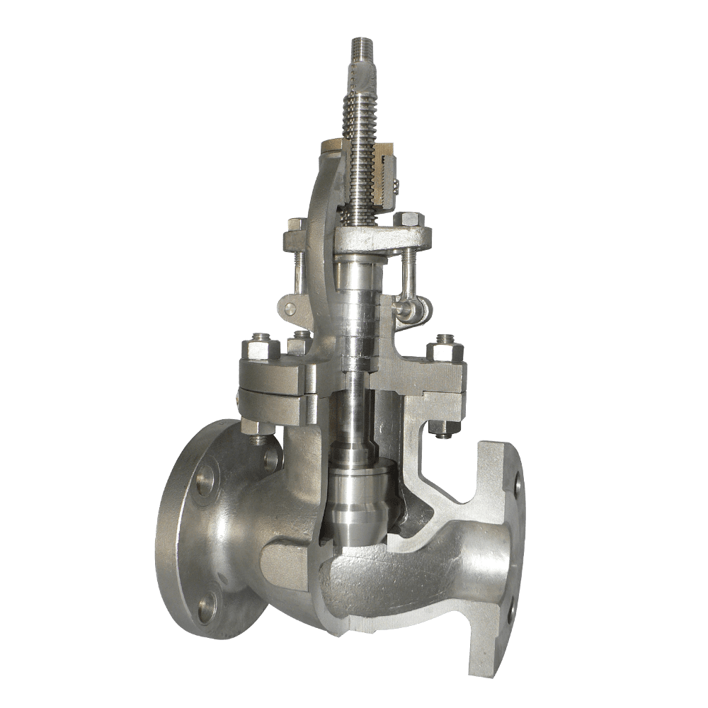
Conventional globe valves typically use a flat or conical disc, with an annular space around the disc and seat. When handling highly viscous fluids or media containing solid particles, these areas can become accumulation points for deposits and coke. The resulting buildup may cause the disc to stick, impair valve operation, and reduce flow control accuracy.
A plug-type globe valve uses a cylindrical plug that fits into an annular seat. As the plug moves up and down, its cylindrical surface maintains close engagement with the seat geometry, helping minimize areas where viscous media and solid deposits can accumulate.
The cylindrical plug serves two functions. For sealing, a PTFE or flexible graphite sealing ring is compressed between the plug and seat assembly to establish the required seal. During valve movement, the plug's sliding action can also help dislodge deposits from the sealing interface, providing a degree of self-cleaning. These features can make plug-type globe valves less susceptible to sticking than conventional globe valves in certain heavy oil, coking, and particulate-laden applications.
Soft-seated designs generally provide tighter shutoff under suitable operating conditions, while metal-to-metal sealing is often preferred for higher-temperature service and applications requiring greater resistance to mechanical wear. The actual leakage performance depends on the sealing design, materials, operating conditions, and applicable testing requirements.
These advantages involve certain trade-offs. The flow path can create greater resistance and pressure drop than a full-bore ball valve or gate valve, so pressure loss should be considered during valve selection. The relatively long plug travel can also increase the number of handwheel turns required for manual operation. Gear operators are therefore worth considering for larger sizes or higher pressure ratings, subject to the actual operating torque and valve design.
The sealing rings are wear components and should be inspected and replaced according to service conditions and maintenance requirements. Before servicing, the valve must be isolated, depressurized, and drained as appropriate. For elevated-temperature applications, an extended bonnet can help protect the packing from excessive heat. In hydrogen service and high-sulfur applications, chromium-molybdenum steel bodies and controlled internal-component hardness may be required, subject to the applicable material and service specifications.
Each valve is designed in accordance with BS 1873 and tested in accordance with API 598.
Heavy oil upgrading, residue hydroprocessing, and viscous oil pipelines: The plug's sliding action helps reduce deposit accumulation and the risk of coking-related sticking.
Coking units and particulate-laden pipelines: The plug can help dislodge deposits from the sealing interface, improving operability in applications where solids accumulation is a concern.
Chemical process lines handling polymerizing or coke-forming media: The internal geometry helps minimize stagnant areas where deposits may accumulate.
Low-flow regulation applications: The valve can be positioned at intermediate openings for flow control, provided the trim design and operating conditions are suitable.
High-temperature steam and hot oil pipelines: An extended bonnet can help reduce heat transfer to the packing assembly.
Hydrogen service and sulfur-containing process streams: Chromium-molybdenum steel bodies and controlled material hardness may be specified according to the applicable process conditions and NACE requirements.
Sealing design: Choose soft-seated sealing rings when tight shutoff is required within the applicable temperature and pressure limits. For higher-temperature service or applications involving abrasive particles, consider metal-to-metal sealing, subject to the required leakage performance.
Material selection: For hydrogen service and sulfur-containing process streams, consider chromium-molybdenum steels such as F22, with material selection, heat treatment, and hardness requirements established by the applicable service specifications. For seawater and chloride-containing media, consider CF8M, CN7M, or suitable Monel alloys after verifying corrosion compatibility.
Operating temperature and bonnet design: For elevated-temperature service, consider an extended bonnet to reduce heat transfer to the packing and help prevent premature packing degradation. Confirm that the bonnet configuration is suitable for the actual operating temperature and installation requirements.
Operating mechanism: For NPS 8 and larger valves or valves rated Class 900 and above, consider a gear operator where required by operating torque and travel requirements. Final actuator or gearbox selection should be based on calculated operating torque, differential pressure, and operating frequency.
Service requirements and pressure drop: For main pipelines requiring pigging compatibility or minimal pressure drop, a full-bore ball valve may be more suitable. Plug-type globe valves generally create greater flow resistance and are better suited to applications where resistance to deposit buildup and reliable operation in challenging media are primary considerations.
At a heavy oil hydroprocessing unit at a Rosneft refinery in Russia, the process involved high-viscosity residue and hydrogen service at Class 900 and an operating temperature of 380°C. The original globe valves experienced sticking and unstable flow regulation due to deposits and difficult operating conditions, contributing to reactor temperature fluctuations and repeated reductions in plant throughput.
Flowork supplied 64 plug-type globe valves in NPS 1–4, Class 900, featuring ASTM A182 F22 chromium-molybdenum steel forged bodies, hardened plug-type trim, Stellite 6 hardfaced sealing surfaces, extended bonnets, flexible graphite packing, and socket-weld ends. The valves were designed in accordance with BS 1873 and underwent shell and closure testing in accordance with API 598, with on-site witnessing by Rosneft's quality control team. Since commissioning in April 2022, the valves have reportedly operated for three consecutive years without sticking. Reactor temperature fluctuations were reduced from ±6°C to ±1.5°C, while valve-related throughput reductions reportedly decreased from five incidents per year to zero.
Q1: What should be done if a plug-type globe valve becomes difficult to operate after prolonged service?
A: Possible causes include deterioration or swelling of the sealing ring, as well as coke and other deposits accumulating between the plug and seat. Isolate and depressurize the valve before inspection. Remove deposits and replace worn or damaged sealing rings as necessary, following the manufacturer's maintenance procedures.
Q2: How often should the sealing rings be replaced?
A: The replacement interval depends on the process medium, operating temperature, frequency of operation, and degree of contamination. Services involving coking or abrasive particles may require more frequent inspection. Increased operating torque, deteriorating shutoff performance, or leakage should prompt an inspection and assessment of the sealing rings.
Q3: Can conventional globe valve sealing rings be used as replacements?
A: No. Replacement rings should be specifically designed for the plug-type globe valve and compatible with the process medium, temperature, pressure, and sealing geometry. Incompatible rings may become displaced, deform prematurely, or fail to provide the required sealing performance.
Q4: Can a plug-type globe valve be used for continuous throttling?
A: It can be used for certain low-flow regulation duties when the valve design and trim are suitable. However, prolonged operation at small openings can accelerate erosion and wear of the sealing components. Verify the allowable throttling range, pressure differential, flow characteristics, and required control accuracy before selecting the valve for continuous regulation.
Class150
Plug Type Globe valve
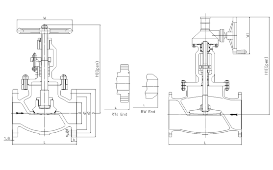
| NPS | in | 2 | 2 1/2 | 3 | 4 | 5 | 6 | 8 | 10 | 12 |
| d | mm | 51 | 64 | 76 | 102 | 127 | 152 | 203 | 254 | 305 |
| L(RF) | mm | 203 | 216 | 241 | 292 | 356 | 406 | 495 | 622 | 698 |
| L(BW) | mm | 203 | 216 | 241 | 292 | 356 | 406 | 495 | 622 | 698 |
| L(RTJ) | mm | 216 | 229 | 254 | 305 | 369 | 419 | 508 | 635 | 711 |
| d1 | mm | 92 | 105 | 127 | 157 | 186 | 216 | 270 | 324 | 381 |
| d2 | mm | 120.5 | 139.5 | 152.5 | 190.5 | 216 | 241.5 | 298.5 | 362 | 432 |
| D | mm | 152 | 178 | 190 | 229 | 254 | 279 | 343 | 406 | 483 |
| b | mm | 16 | 18 | 19 | 24 | 24 | 26 | 29 | 31 | 32 |
| n-Фd | mm | 4-19 | 4-19 | 4-19 | 8-19 | 8-22 | 8-22 | 8-22 | 12-25 | 12-25 |
| H | mm | 330 | 360 | 390 | 445 | 480 | 520 | 600 | 773 | 880 |
| H1 | mm |
|
|
|
|
| 556 | 658 | 805 | 955 |
| W | mm | 200 | 200 | 250 | 300 | 350 | 350 | 500 | 500 | 550 |
| W1 | mm |
|
|
|
|
| 310 | 310 | 460 | 460 |
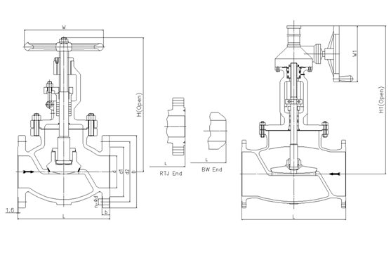
| NPS | in | 2 | 2 1/2 | 3 | 4 | 5 | 6 | 8 | 10 | 12 |
| d | mm | 51 | 64 | 76 | 102 | 127 | 152 | 203 | 254 | 305 |
| L(RF) | mm | 267 | 292 | 318 | 356 | 400 | 444 | 559 | 622 | 711 |
| L(BW) | mm | 267 | 292 | 318 | 356 | 400 | 444 | 559 | 622 | 711 |
| L(RTJ) | mm | 283 | 308 | 333 | 371 | 416 | 460 | 575 | 638 | 727 |
| d1 | mm | 92 | 105 | 127 | 157 | 186 | 216 | 270 | 324 | 381 |
| d2 | mm | 127 | 149 | 168.5 | 200 | 235 | 270 | 330 | 387.5 | 451 |
| D | mm | 165 | 190 | 210 | 254 | 279 | 318 | 381 | 445 | 521 |
| b | mm | 23 | 26 | 29 | 32 | 35 | 37 | 42 | 48 | 51 |
| n-Фd | mm | 8-19 | 8-22 | 8-22 | 8-22 | 8-22 | 12-22 | 12-25 | 16-29 | 16-32 |
| H | mm | 385 | 420 | 440 | 515 | 580 | 660 | 900 | 950 | 1030 |
| H1 | mm |
|
|
|
|
| 690 | 950 | 990 | 1080 |
| W | mm | 250 | 250 | 300 | 350 | 450 | 500 | 500 | 550 | 550 |
| W1 | mm |
|
|
|
|
| 310 | 460 | 460 | 460 |
Class600
Plug Type Globe valve
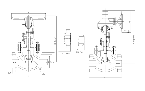
| NPS | in | 2 | 2 1/2 | 3 | 4 | 5 | 6 | 8 | 10 | 12 |
| d | mm | 51 | 64 | 76 | 102 | 127 | 152 | 200 | 248 | 298 |
| L(RF) | mm | 292 | 330 | 356 | 432 | 508 | 559 | 660 | 787 | 838 |
| L(BW) | mm | 292 | 330 | 356 | 432 | 508 | 559 | 660 | 787 | 838 |
| L(RTJ) | mm | 295 | 333 | 359 | 435 | 511 | 562 | 664 | 791 | 841 |
| d1 | mm | 92 | 105 | 127 | 157 | 186 | 216 | 270 | 324 | 381 |
| d2 | mm | 127 | 149 | 168.5 | 216 | 267 | 292 | 349 | 432 | 489 |
| D | mm | 165 | 190 | 210 | 273 | 330 | 356 | 419 | 508 | 559 |
| b | mm | 26 | 29 | 32 | 38 | 45 | 48 | 56 | 64 | 67 |
| n-Фd | mm | 8-19 | 8-22 | 8-22 | 8-25 | 8-29 | 12-29 | 12-32 | 16-35 | 20-35 |
| H | mm | 360 | 410 | 465 | 545 | 625 | 785 | 930 |
|
|
| H1 | mm |
|
|
| 575 | 660 | 820 | 960 | 1040 | 1280 |
| W | mm | 250 | 300 | 350 | 400 | 500 | 550 | 650 |
|
|
| W1 | mm |
|
|
| 310 | 310 | 460 | 460 | 610 | 610 |
Class900
Plug Type Globe valve
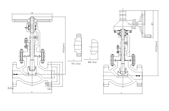
| NPS | in | 2 | 2 1/2 | 3 | 4 | 5 | 6 | 8 | 10 |
| d | mm | 47 | 57 | 73 | 98 | 121 | 146 | 190 | 234 |
| L(RF) | mm | 368 | 419 | 381 | 457 | 559 | 610 | 737 | 838 |
| L(BW) | mm | 368 | 419 | 381 | 457 | 559 | 610 | 737 | 838 |
| L(RTJ) | mm | 371 | 422 | 384 | 460 | 562 | 613 | 740 | 841 |
| d1 | mm | 92 | 105 | 127 | 157 | 186 | 216 | 270 | 324 |
| d2 | mm | 165 | 190.5 | 190.5 | 235 | 279.4 | 317.5 | 393.7 | 469.9 |
| D | mm | 216 | 244 | 241 | 292 | 349 | 381 | 470 | 545 |
| b | mm | 38.5 | 41.5 | 38.5 | 44.5 | 51 | 56 | 64 | 70 |
| n-Фd | mm | 8-26 | 8-29 | 8-26 | 8-32 | 8-35 | 12-32 | 12-39 | 16-39 |
| H | mm | 480 | 520 | 564 | 685 | 780 | 950 |
|
|
| H1 | mm |
|
| 630 | 720 | 840 | 1015 | 1100 | 1185 |
| W | mm | 350 | 350 | 400 | 450 | 550 | 650 |
|
|
| W1 | mm |
|
| 310 | 310 | 460 | 460 | 610 | 610 |
Class1500
Plug Type Globe valve
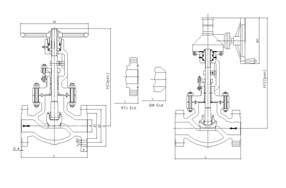
| NPS | in | 2 | 2 1/2 | 3 | 4 | 5 | 6 | 8 |
| d | mm | 47 | 57 | 70 | 92 | 111 | 136 | 178 |
| L(RF) | mm | 368 | 419 | 470 | 546 | 673 | 705 | 832 |
| L(BW) | mm | 368 | 419 | 470 | 546 | 673 | 705 | 832 |
| L(RTJ) | mm | 371 | 422 | 473 | 549 | 676 | 711 | 841 |
| d1 | mm | 92 | 105 | 127 | 157 | 186 | 216 | 270 |
| d2 | mm | 165 | 190.5 | 203.2 | 241.3 | 292.1 | 317.5 | 393.7 |
| D | mm | 216 | 244 | 267 | 311 | 375 | 394 | 483 |
| b | mm | 38.5 | 41.5 | 48 | 54 | 73.5 | 83 | 92.9 |
| n-Фd | mm | 8-26 | 8-29 | 8-32 | 8-35 | 8-42 | 12-39 | 12-45 |
| H | mm | 592 | 660 | 692 |
|
|
|
|
| H1 | mm |
|
|
| 907 | 950 | 1015 | 1145 |
| W | mm | 350 | 400 | 500 |
|
|
|
|
| W1 | mm |
|
|
| 460 | 610 | 610 | 610 |
API Trim NO.
Table
|
No |
Seat |
Gate、disc 、ball or body |
Stem |
No |
Seat |
Gate、disc 、ball or body |
Stem | |
| 01 | 13Cr | 13Cr | 13Cr | 31 | STELLITE | 321SS | 321SS | |
| 02 | 304SS | 304SS | 304SS | 32 | STELLITE | STELLITE | 321SS | |
| 03 | 310SS | 310SS | 310SS | 33 | 347SS | 347SS | 347SS | |
| 04 | HARD 13Cr | HARD 13Cr | 13Cr | 34 | STELLITE | 347SS | 347SS | |
| 05 | STELLITE | STELLITE | 13Cr | 35 | NICKEL ALLOY | 13Cr | 13Cr | |
| 06 | Cu-Ni | 13Cr | 13Cr | 36 | A105/PTFE | A105+ENP | A105+ENP | |
| 07 | 13Cr | HARD 13Cr | 13Cr | 37 | A105/PTFE | WCB+ENP | A105+ENP | |
| 08 | STELLITE | 13Cr | 13Cr | 38 | 13Cr/PTFE | 13Cr | 13Cr | |
| 09 | Cu-Ni | Cu-Ni | Cu-Ni | 39 | 304SS/PTFE | 304SS | 304SS | |
| 10 | 316SS | 316SS | 316SS | 40 | 316SS/PTFE | 316SS | 316SS | |
| 11 | Cu-Ni | STELLITE | Cu-Ni | 41 | A105/RPTFE | A105+ENP | A105+ENP | |
| 12 | STELLITE | 316SS | 316SS | 42 | A105/RPTFE | WCB+ENP | A105+ENP | |
| 13 | ALLOY 20 | ALLOY 20 | ALLOY 20 | 43 | 13Cr/RPTFE | 13Cr | 13Cr | |
| 14 | STELLITE | ALLOY 20 | ALLOY 20 | 44 | 304SS/RPTFE | 304SS | 304SS | |
| 15 | STELLITE | STELLITE | 304SS | 45 | 316SS/RPTFE | 316SS | 316SS | |
| 16 | STELLITE | STELLITE | 316SS | 46 | A105/NYLON | A105+ENP | A105+ENP | |
| 17 | STELLITE | STELLITE | 347SS | 47 | A105/NYLON | WCB+ENP | A105+ENP | |
| 18 | STELLITE | STELLITE | ALLOY 20 | 48 | A105/NYLON | 304SS | 304SS | |
| 19 | MONEL | MONEL | MONEL | 49 | A105/NYLON | 316SS | 316SS | |
| 20 | BRONZE | BRONZE | 13Cr | 50 | 13Cr/NYLON | 13Cr | 13Cr | |
| 21 | HASTELLOY B | HASTELLOY B | HASTELLOY B | 51 | 304SS/NYLON | 304SS | 304SS | |
| 22 |
| HASTELLOY C | HASTELLOY C | 52 | 316SS/NYLON | 316SS | 316SS | |
| 23 | STELLITE | 304SS | 304SS | 53 | A105/PEEK | A105+ENP | A105+ENP | |
| 24 | 304LSS | 304LSS | 304LSS | 54 | A105/PEEK | WCB+ENP | A105+ENP | |
| 25 | STELLITE | 304LSS | 304LSS | 55 | 13Cr/PEEK | 13Cr | 13Cr | |
| 26 | STELLITE | STELLITE | 304LSS | 56 | 304SS/PEEK | 304SS | 304SS | |
| 27 | 316LSS | 316LSS | 316LSS | 57 | 316SS/PEEK | 316SS | 316SS | |
| 28 | STELLITE | 316LSS | 316LSS |
|
|
|
|
|
| 29 | STELLITE | STELLITE | 316LSS |
|
|
| ||
| 30 | 321SS | 321SS | 321SS |
|
|
|
| |
Note:please indicate it directly in the
order for the internal part’smaterial uncovered in the table
 Optimized by Seraphinite Accelerator