



 Skip to content

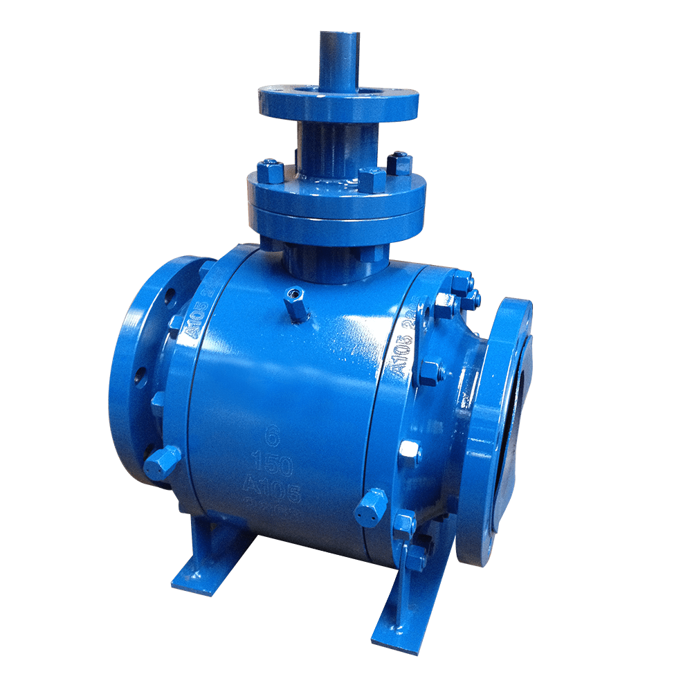
The distinction between a trunnion-mounted ball valve and a floating ball valve lies not in valve size, but in the load path of the medium-induced thrust. In a floating ball valve, sealing force is generated by the medium pushing the ball against the downstream seat. As pressure increases, the sealing force increases accordingly, and so does the operating torque. For floating ball valves above NPS 8 in high-pressure service, operating torque can reach several thousand N·m, while ball translation during operation can also cause circumferential wear of the sealing surfaces.
The trunnion-mounted design changes this load path. The ball is supported by upper and lower trunnions and bearings, with the medium-induced thrust transferred through the trunnions to the valve body. The ball rotates through 90° without translational movement. Sealing is provided jointly by the preloaded seat springs and medium pressure. Operating torque is primarily determined by the coefficient of friction at the sealing surfaces and does not increase linearly with valve size and pressure. Even an NPS 24, Class 900 valve can therefore be operated with relatively low torque.
The forged valve body is another key requirement. Thick sections of large castings are prone to shrinkage cavities and porosity, and microscopic defects can become crack initiation sites under high-pressure, sour-service conditions. This series uses an integral A105 forged valve body with a full-bore flow passage, allowing pigging operations to pass through the valve without obstruction.
The seats feature a double-piston effect design with an automatic cavity pressure relief function, allowing abnormal pressure in the body cavity to be relieved to the upstream side. Grease injection fittings are provided at the seats and stem, allowing temporary field sealing in the event of minor leakage.
The ball and sealing surfaces are selected according to the service medium: F51/F53 duplex stainless steel substrates with hard-chrome-plated balls are used for chloride-containing sour service; F11/F22 are used for high-temperature service; and LF2/LF3 are used for low-temperature service. Each valve undergoes shell and sealing tests in accordance with API 598. DBB functional test records, material certificates, and non-destructive examination reports can also be provided.
High-pressure natural gas and sour gas transmission pipelines: trunnion-mounted construction provides low operating torque in Class 600 and above service and can be equipped with actuators for remote shutdown.
Oilfield custody metering stations: double block and bleed (DBB) construction allows independent cavity bleeding for online verification and double isolation.
Sour crude oil pipelines containing H₂S: F51/F53 duplex stainless steel substrates can be configured for sour-service applications in accordance with NACE MR0175.
Condensate and light hydrocarbon pipelines: integral forged construction eliminates casting defects and withstands erosion from high-pressure, low-viscosity media.
High-pressure process piping on offshore platforms: duplex stainless steel with metal-seated construction is used for chloride-containing seawater and sour gas service.
Design selection: For NPS 8 and above or Class 600 and above, a trunnion-mounted design is preferred. Floating ball valves may be used for small-bore, low-pressure service at a lower cost.
Seat configuration: Select double block and bleed (DBB) seats when online verification or double isolation is required. For fire-risk applications, confirm compliance with API 607 fire-safe requirements and the anti-static continuity design.
Emergency measures: Grease injection fittings are provided at the seats and stem, allowing temporary sealing by on-site grease injection in the event of abnormal leakage. Sealant should be replenished periodically in accordance with the maintenance manual.
Materials and operation: A105 is used for conventional oil and gas service, F51/F53 for chloride-containing seawater, and F11/F22 for high-temperature service. For NPS 12 and above, a gearbox or actuator is recommended to reduce opening and closing time.
Q: How can a trunnion-mounted ball valve be distinguished from a floating ball valve?
A: A floating ball valve relies on medium pressure to push the ball against the downstream seat. The sealing force increases with pressure, and operating torque increases accordingly. In a trunnion-mounted ball valve, the upper and lower trunnions and bearings absorb the thrust, while the ball only rotates without translation. The relationship between operating torque and valve size or pressure is therefore much less pronounced.
Q: What is the purpose of a DBB design?
A: Double block and bleed allows the body cavity to be independently bled. When both seats are closed, the cavity can be checked for residual pressure, making the design suitable for metering pipelines requiring online verification or double isolation.
Q: What are the seat grease injection fittings used for?
A: They are used to inject sealant locally for temporary sealing when minor leakage occurs, and to replenish lubrication for the seats and stem during long-term operation, in accordance with the maintenance manual.
At the DNO Iraq Tawke Oilfield export metering station in Iraq, sour crude oil containing 0.8% H₂S and chlorides was transported under Class 900 service. The original ball valves experienced a sharp increase in operating torque within 18 months due to seat swelling and deformation. Each failure required switching to the bypass line, resulting in an approximately 30,000-tonne loss of export volume.
Flowork supplied 36 NPS 8–16, Class 900 forged trunnion mounted ball valves featuring A105 integral forged valve bodies, full-bore flow passages, hard-chrome-plated balls, Devlon V seats, and double block and bleed (DBB) construction with automatic cavity pressure relief seats. The valves were designed in accordance with API 6D and tested in accordance with API 598, with on-site inspection witnessed by DNO.
Since commissioning in April 2022, the valves have operated continuously for three years with zero leakage and zero sticking. Metering deviation was reduced from ±3% to ±0.5%, significantly improving the stability of export metering.
Class150
Forged trunnion mounted ball valve

| NPS | in | 2 | 2 1/2 | 3 | 4 | 6 | 8 | 10 | 12 | 14 | 16 | 18 | 20 | 24 |
| d | mm | 51 | 64 | 76 | 102 | 152 | 203 | 254 | 305 | 337 | 387 | 438 | 489 | 591 |
| L(RF) | mm | 178 | 190 | 203 | 229 | 394 | 457 | 533 | 610 | 686 | 762 | 864 | 914 | 1016 |
| d1 | mm | 92 | 105 | 127 | 157 | 216 | 270 | 324 | 381 | 413 | 470 | 533 | 584 | 692 |
| d2 | mm | 120.5 | 139.5 | 152.5 | 190.5 | 241.5 | 298.5 | 362 | 432 | 476 | 540 | 578 | 635 | 749.5 |
| D | mm | 152 | 178 | 190 | 229 | 279 | 343 | 406 | 483 | 533 | 597 | 635 | 699 | 813 |
| b | mm | 16 | 18 | 19 | 24 | 26 | 29 | 31 | 32 | 35 | 37 | 40 | 43 | 48 |
| n-Фd | mm | 4-19 | 4-19 | 4-19 | 8-19 | 8-22 | 8-22 | 12-25 | 12-25 | 12-29 | 16-29 | 16-32 | 20-32 | 20-35 |
| H | mm | 176 | 200 | 215 | 252 | 330 | 448 | 505 | 556 | 620 | 700 | 750 | 805 | 1110 |
| W | mm | 350 | 400 | 400 | 500 | 1000 | 300 | 350 | 400 | 500 | 500 | 500 | 500 | 500 |
Class300
Forgedtrunnion mounted ball valve

| NPS | in | 2 | 2 1/2 | 3 | 4 | 6 | 8 | 10 | 12 | 14 | 16 | 18 | 20 | 24 |
| d | mm | 51 | 64 | 76 | 102 | 152 | 203 | 254 | 305 | 337 | 387 | 432 | 483 | 584 |
| L(RF) | mm | 216 | 241 | 283 | 305 | 403 | 502 | 568 | 648 | 762 | 838 | 914 | 991 | 1143 |
| d1 | mm | 92 | 105 | 127 | 157 | 216 | 270 | 324 | 381 | 413 | 470 | 533 | 584 | 692 |
| d2 | mm | 127 | 149 | 168.5 | 200 | 270 | 330 | 387.5 | 451 | 514.5 | 571.5 | 628.5 | 686 | 813 |
| D | mm | 165 | 190 | 210 | 254 | 318 | 381 | 445 | 521 | 584 | 648 | 711 | 775 | 914 |
| b | mm | 23 | 26 | 29 | 32 | 37 | 42 | 48 | 51 | 54 | 58 | 61 | 64 | 70 |
| n-Фd | mm | 8-19 | 8-22 | 8-22 | 8-22 | 12-22 | 12-25 | 16-29 | 16-32 | 20-32 | 20-35 | 24-35 | 24-35 | 24-41 |
| H | mm | 176 | 200 | 215 | 252 | 330 | 448 | 505 | 556 | 620 | 700 | 750 | 805 | 1110 |
| W | mm | 350 | 400 | 400 | 500 | 1000 | 300 | 350 | 400 | 500 | 500 | 500 | 500 | 500 |
Class600
Forgedtrunnion mounted ball valve

| NPS | in | 2 | 3 | 4 | 5 | 6 | 8 | 10 | 12 | 14 | 16 | 18 | 20 | 24 |
| d | mm | 51 | 76 | 102 | 127 | 152 | 200 | 248 | 298 | 327 | 375 | 419 | 464 | 559 |
| L(RF) | mm | 292 | 356 | 432 | 508 | 559 | 660 | 787 | 838 | 889 | 991 | 1092 | 1194 | 1397 |
| d1 | mm | 92 | 127 | 157 | 186 | 216 | 270 | 324 | 381 | 413 | 470 | 533 | 584 | 692 |
| d2 | mm | 127 | 168.5 | 216 | 267 | 292 | 349 | 432 | 489 | 527 | 603 | 654 | 724 | 838 |
| D | mm | 165 | 210 | 273 | 330 | 356 | 419 | 508 | 559 | 603 | 686 | 743 | 813 | 940 |
| b | mm | 26 | 32 | 38 | 45 | 48 | 56 | 64 | 67 | 70 | 77 | 83 | 89 | 102 |
| n-Фd | mm | 8-19 | 8-22 | 8-25 | 8-29 | 12-29 | 12-32 | 16-35 | 20-35 | 20-38 | 20-41 | 20-44 | 24-44 | 24-52 |
| H | mm | 192 | 279 | 315 | 320 | 323 | 381 | 518 | 568 | 665 | 730 | 795 | 825 | 973 |
| W | mm | 600 | 1000 | 1500 | 1500 | 1500 | 500 | 500 | 500 | 500 | 500 | 500 | 500 | 500 |
Class900
Forgedtrunnion mounted ball valve

| NPS | in | 2 | 3 | 4 | 5 | 6 | 8 | 10 | 12 | 14 | 16 | 18 | 20 | 24 |
| d | mm | 47 | 73 | 98 | 121 | 146 | 190 | 234 | 282 | 311 | 354 | 400 | 444 | 533 |
| L(RF) | mm | 368 | 381 | 457 | 559 | 610 | 737 | 838 | 965 | 1029 | 1130 | 1219 | 1321 | 1549 |
| L(RTJ) | mm | 371 | 384 | 460 | 562 | 613 | 740 | 841 | 968 | 1039 | 1140 | 1232 | 1334 | 1568 |
| d1 | mm | 92 | 127 | 157 | 186 | 216 | 270 | 324 | 381 | 413 | 470 | 533 | 584 | 692 |
| d2 | mm | 165 | 190.5 | 235 | 279.4 | 317.5 | 393.7 | 469.9 | 533.4 | 558.8 | 615.9 | 685.8 | 749.3 | 901.7 |
| D | mm | 216 | 241 | 292 | 349 | 381 | 470 | 545 | 610 | 640 | 705 | 785 | 855 | 1040 |
| b | mm | 38.5 | 38.5 | 44.5 | 51 | 56 | 64 | 70 | 79.5 | 86 | 89 | 102 | 108 | 140 |
| n-Фd | mm | 8-26 | 8-26 | 8-32 | 8-35 | 12-32 | 12-39 | 16-39 | 20-39 | 20-42 | 20-45 | 20-51 | 20-54 | 20-67 |
| H | mm | 192 | 279 | 315 | 320 | 323 | 381 | 518 | 568 | 665 | 730 | 795 | 825 | 973 |
| W | mm | 600 | 1000 | 1500 | 1500 | 500 | 500 | 500 | 500 | 500 | 500 | 500 | 500 | 500 |
API Trim NO.
Table
|
No |
Seat |
Gate、disc 、ball or body |
Stem |
No |
Seat |
Gate、disc 、ball or body |
Stem | |
| 01 | 13Cr | 13Cr | 13Cr | 31 | STELLITE | 321SS | 321SS | |
| 02 | 304SS | 304SS | 304SS | 32 | STELLITE | STELLITE | 321SS | |
| 03 | 310SS | 310SS | 310SS | 33 | 347SS | 347SS | 347SS | |
| 04 | HARD 13Cr | HARD 13Cr | 13Cr | 34 | STELLITE | 347SS | 347SS | |
| 05 | STELLITE | STELLITE | 13Cr | 35 | NICKEL ALLOY | 13Cr | 13Cr | |
| 06 | Cu-Ni | 13Cr | 13Cr | 36 | A105/PTFE | A105+ENP | A105+ENP | |
| 07 | 13Cr | HARD 13Cr | 13Cr | 37 | A105/PTFE | WCB+ENP | A105+ENP | |
| 08 | STELLITE | 13Cr | 13Cr | 38 | 13Cr/PTFE | 13Cr | 13Cr | |
| 09 | Cu-Ni | Cu-Ni | Cu-Ni | 39 | 304SS/PTFE | 304SS | 304SS | |
| 10 | 316SS | 316SS | 316SS | 40 | 316SS/PTFE | 316SS | 316SS | |
| 11 | Cu-Ni | STELLITE | Cu-Ni | 41 | A105/RPTFE | A105+ENP | A105+ENP | |
| 12 | STELLITE | 316SS | 316SS | 42 | A105/RPTFE | WCB+ENP | A105+ENP | |
| 13 | ALLOY 20 | ALLOY 20 | ALLOY 20 | 43 | 13Cr/RPTFE | 13Cr | 13Cr | |
| 14 | STELLITE | ALLOY 20 | ALLOY 20 | 44 | 304SS/RPTFE | 304SS | 304SS | |
| 15 | STELLITE | STELLITE | 304SS | 45 | 316SS/RPTFE | 316SS | 316SS | |
| 16 | STELLITE | STELLITE | 316SS | 46 | A105/NYLON | A105+ENP | A105+ENP | |
| 17 | STELLITE | STELLITE | 347SS | 47 | A105/NYLON | WCB+ENP | A105+ENP | |
| 18 | STELLITE | STELLITE | ALLOY 20 | 48 | A105/NYLON | 304SS | 304SS | |
| 19 | MONEL | MONEL | MONEL | 49 | A105/NYLON | 316SS | 316SS | |
| 20 | BRONZE | BRONZE | 13Cr | 50 | 13Cr/NYLON | 13Cr | 13Cr | |
| 21 | HASTELLOY B | HASTELLOY B | HASTELLOY B | 51 | 304SS/NYLON | 304SS | 304SS | |
| 22 |
| HASTELLOY C | HASTELLOY C | 52 | 316SS/NYLON | 316SS | 316SS | |
| 23 | STELLITE | 304SS | 304SS | 53 | A105/PEEK | A105+ENP | A105+ENP | |
| 24 | 304LSS | 304LSS | 304LSS | 54 | A105/PEEK | WCB+ENP | A105+ENP | |
| 25 | STELLITE | 304LSS | 304LSS | 55 | 13Cr/PEEK | 13Cr | 13Cr | |
| 26 | STELLITE | STELLITE | 304LSS | 56 | 304SS/PEEK | 304SS | 304SS | |
| 27 | 316LSS | 316LSS | 316LSS | 57 | 316SS/PEEK | 316SS | 316SS | |
| 28 | STELLITE | 316LSS | 316LSS |
|
|
|
|
|
| 29 | STELLITE | STELLITE | 316LSS |
|
|
| ||
| 30 | 321SS | 321SS | 321SS |
|
|
|
| |
Note:please indicate it directly in the
order for the internal part’smaterial uncovered in the table


 Optimized by Seraphinite Accelerator