



 Skip to content

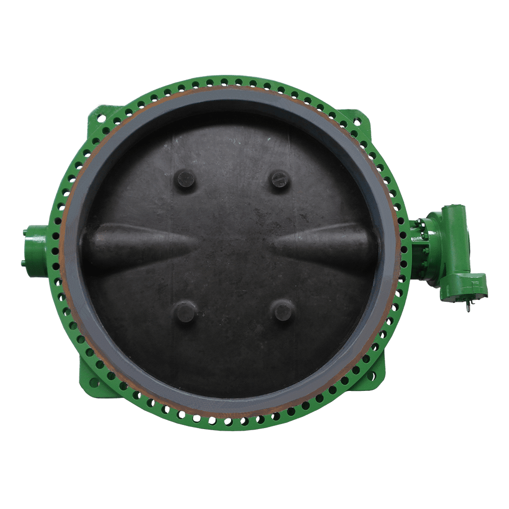
As valve diameter increases, the advantages and engineering challenges of butterfly valves become more pronounced. Their relatively low weight and compact construction can reduce equipment handling requirements and installation costs. For example, a DN 2000 butterfly valve can weigh substantially less than a gate valve of the same nominal diameter, depending on the design and pressure rating. However, larger discs also create greater structural and operating demands. Hydraulic forces acting on the disc increase with its projected area, while the required operating torque depends on differential pressure, disc geometry, bearing friction, seal design, and other factors. Disc stiffness and resistance to deformation therefore become increasingly important as valve size increases.
Large diameter butterfly valves commonly use double-offset or triple-offset designs. In a double-offset valve, the stem axis is offset relative to the disc and seat geometry, allowing the disc to move away from the seat shortly after opening. A triple-offset design introduces an additional geometric offset that produces a cam-like, non-rubbing seating action. These configurations reduce sliding contact between the sealing surfaces, helping lower operating torque and minimize wear.
Depending on the application, butterfly valves can use resilient soft seats or metal-seated designs. Soft-seated valves are suitable for many ambient-temperature water applications requiring tight shutoff, provided the seat material is compatible with the operating conditions. Triple-offset metal-seated designs commonly use layered metal sealing elements, sometimes incorporating graphite layers, to provide a combination of flexibility, temperature resistance, and fire-safe performance where appropriately designed and qualified.
Large diameter butterfly valves are generally equipped with gear operators or powered actuators. Manual operation can require numerous handwheel turns, and adequate clearance should be provided for operation, inspection, and lifting equipment during maintenance. Soft seats are sensitive to foreign particles and installation debris; welding slag or sharp solids can damage the sealing surface. The pipeline should therefore be thoroughly cleaned and flushed before commissioning.
Prolonged operation at intermediate openings can expose the disc and seat to high local velocities, turbulence, vibration, and erosion. Unless the valve is specifically selected and qualified for throttling service, full-open or full-closed operation is generally preferred.
For seawater applications, CF8M stainless steel or C95800 nickel-aluminum bronze may be considered for the valve body and disc, subject to corrosion assessment. The stem material should be selected for the chloride environment and mechanical loading, with suitable protective coatings or marine-growth control measures considered where required.
Each valve is designed in accordance with API 609 and tested in accordance with API 598.
Circulating water and cooling water headers: Large flow capacity, quarter-turn operation, and reduced weight compared with many gate valve configurations of equivalent size.
Seawater cooling pipelines: Corrosion-resistant body and disc materials, suitable stem alloys, and protective measures against marine growth.
Large diameter water supply and wastewater treatment pipelines: Compact construction and reduced installation and handling requirements.
Flue gas desulfurization, exhaust gas, and ventilation systems: Eccentric designs with suitable metal seats for demanding temperature and corrosion conditions.
Pump stations and valve stations requiring rapid isolation: Gear-operated or actuated butterfly valves for efficient operation in large-diameter pipelines.
Valve design and sealing: For ambient-temperature clean water, consider a concentric butterfly valve with a resilient soft seat. For higher temperatures, abrasive media, or more demanding operating conditions, consider double-offset or triple-offset metal-seated designs, subject to the required leakage performance.
Stem and body materials: Select the stem material according to operating torque, mechanical strength, and corrosion exposure. For seawater, consider suitable duplex stainless steel stems and corrosion-resistant body and disc materials such as CF8M or C95800, after verifying their suitability for the specific seawater conditions.
Operating mechanism: For valves DN 600 and larger, or installations where the valve is positioned at an elevated or difficult-to-access location, consider a gear operator or powered actuator. Size the operating mechanism based on the maximum required torque under the specified differential pressure and operating conditions.
Installation and pipeline cleaning: Thoroughly clean and flush the pipeline before commissioning. Tighten flange bolts in a diagonal, crosswise sequence using the specified procedure to achieve even gasket compression and avoid damaging the sealing components. Confirm correct valve alignment and installation clearances.
Pressure drop assessment: Butterfly valves generally introduce more flow resistance than a fully open, full-bore gate valve or ball valve of comparable nominal size. Include disc-related pressure loss in the hydraulic calculation to ensure that the valve meets the system's flow and pressure requirements.
At the seawater cooling water header of a CNOOC International Limited project in Oman, the system operated with DN 2000, PN 10 high-salinity seawater containing marine organisms. The original valves experienced sticking due to seawater corrosion and marine growth accumulation on the disc and associated components. After approximately 11 months of service, the valves could no longer achieve full closure, requiring unplanned cleaning and maintenance.
Flowork supplied 34 large diameter double-offset butterfly valves in DN 1200–2400, PN 10, featuring CF8M stainless steel bodies and discs, 2205 duplex stainless steel stems, PTFE/stainless steel composite multilayer sealing elements, protective coatings against marine growth, and gear operators. The valves were designed in accordance with API 609 Category B and underwent shell and sealing tests in accordance with API 598, with on-site witnessing by CNOOC International's engineering team. Since commissioning in March 2022, the valves have reportedly operated for three consecutive years without sticking or leakage. Unplanned shutdowns for marine-growth removal were reduced from approximately four times per year to zero, while cooling water system availability reportedly increased to 99.5% and power generation availability to 99.2%.
Q1: What should be done if a large diameter butterfly valve still leaks slightly after closing?
A: Common causes include debris trapped between the disc and seat, damage to the sealing ring, or incorrect travel limits that prevent the disc from reaching its fully closed position. First, verify that no foreign objects are obstructing the disc. Then inspect the seat, sealing surfaces, actuator settings, and mechanical stops in accordance with the manufacturer's maintenance procedures.
Q2: How should a butterfly valve with a seized stem in seawater service be addressed?
A: Possible causes include corrosion of the stem, coating degradation, bearing problems, or marine growth affecting moving components. Isolate the valve and make the system safe before inspection. Assess the stem material, bearing arrangement, and protective coating, and replace unsuitable or damaged components with materials and protection systems appropriate for the seawater environment.
Q3: Why does a butterfly valve vibrate or produce unusual noise when fully open?
A: Possible causes include improper installation alignment, insufficient clearance between the disc and adjacent piping components, excessive flow velocity, or hydraulic turbulence. Prolonged operation at intermediate openings can also cause vibration and erosion. Check installation geometry and operating conditions, and confirm that the valve is being used within its specified operating range.
Q4: What precautions should be taken when replacing a soft seat?
A: Isolate, depressurize, and drain the pipeline before removing the seat. Replace it with the correct part number and material specification, following the manufacturer's installation procedure. Thoroughly clean the pipeline and remove welding slag and other debris before returning the valve to service to prevent damage to the new seat.
Class150
Big size Butterfly Valves
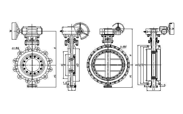
| NPS | in | 2 | 3 | 4 | 6 | 8 | 10 | 12 | 14 | 16 | 18 | 20 | 24 |
| d | mm | 51 | 76 | 102 | 152 | 203 | 254 | 305 | 337 | 387 | 438 | 489 | 591 |
| L(RF) | mm | 43 | 48 | 54 | 57 | 64 | 71 | 81 | 92 | 102 | 114 | 127 | 154 |
| \L1(RF) | mm | 108 | 114 | 127 | 140 | 152 | 165 | 178 | 190 | 216 | 222 | 229 | 267 |
| d1 | mm | 92 | 127 | 157 | 216 | 270 | 324 | 381 | 413 | 470 | 533 | 584 | 692 |
| d2 | mm | 120.5 | 152.5 | 190.5 | 241.5 | 298.5 | 362 | 432 | 476 | 540 | 578 | 635 | 749.5 |
| D | mm | 152 | 190 | 229 | 279 | 343 | 406 | 483 | 533 | 597 | 635 | 699 | 813 |
| b | mm | 16 | 19 | 24 | 26 | 29 | 31 | 32 | 35 | 37 | 40 | 43 | 48 |
| n-Фd | mm | 4-19 | 4-19 | 8-19 | 8-22 | 8-22 | 12-25 | 12-25 | 12-29 | 16-29 | 16-32 | 20-32 | 20-35 |
| H | mm | 225 | 255 | 285 | 332 | 386 | 427 | 498 | 510 | 540 | 585 | 642 | 693 |
| H1 | mm | 112 | 126 | 146 | 170 | 218 | 245 | 290 | 316 | 352 | 386 | 415 | 482 |
| W | mm | 300 | 300 | 300 | 300 | 300 | 300 | 500 | 500 | 600 | 600 | 600 | 600 |
Class300
Big size Butterfly Valves
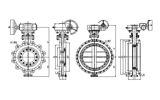
| NPS | in | 3 | 4 | 6 | 8 | 10 | 12 | 14 | 16 | 18 | 20 | 24 |
| d | mm | 76 | 102 | 152 | 203 | 254 | 305 | 337 | 387 | 432 | 483 | 584 |
| L(RF) | mm | 48 | 54 | 59 | 73 | 83 | 92 | 117 | 133 | 149 | 159 | 181 |
| \L1(RF) | mm | 114 | 127 | 140 | 152 | 165 | 178 | 190 | 216 | 222 | 229 | 267 |
| d1 | mm | 127 | 157 | 216 | 270 | 324 | 381 | 413 | 470 | 533 | 584 | 692 |
| d2 | mm | 168.5 | 200 | 270 | 330 | 387.5 | 451 | 514.5 | 571.5 | 628.5 | 686 | 813 |
| D | mm | 210 | 254 | 318 | 381 | 445 | 521 | 584 | 648 | 711 | 775 | 914 |
| b | mm | 29 | 32 | 37 | 42 | 48 | 51 | 54 | 58 | 61 | 64 | 70 |
| n-Фd | mm | 8-22 | 8-22 | 12-22 | 12-25 | 16-29 | 16-32 | 20-32 | 20-35 | 24-35 | 24-35 | 24-41 |
| H | mm | 265 | 290 | 355 | 418 | 456 | 498 | 547 | 582 | 651 | 704 | 780 |
| H1 | mm | 130 | 150 | 185 | 236 | 273 | 313 | 338 | 392 | 420 | 465 | 532 |
| W | mm | 300 | 300 | 300 | 500 | 500 | 600 | 600 | 600 | 600 | 600 | 600 |
API Trim NO.
Table
|
No |
Seat |
Gate、disc 、ball or body |
Stem |
No |
Seat |
Gate、disc 、ball or body |
Stem | |
| 01 | 13Cr | 13Cr | 13Cr | 31 | STELLITE | 321SS | 321SS | |
| 02 | 304SS | 304SS | 304SS | 32 | STELLITE | STELLITE | 321SS | |
| 03 | 310SS | 310SS | 310SS | 33 | 347SS | 347SS | 347SS | |
| 04 | HARD 13Cr | HARD 13Cr | 13Cr | 34 | STELLITE | 347SS | 347SS | |
| 05 | STELLITE | STELLITE | 13Cr | 35 | NICKEL ALLOY | 13Cr | 13Cr | |
| 06 | Cu-Ni | 13Cr | 13Cr | 36 | A105/PTFE | A105+ENP | A105+ENP | |
| 07 | 13Cr | HARD 13Cr | 13Cr | 37 | A105/PTFE | WCB+ENP | A105+ENP | |
| 08 | STELLITE | 13Cr | 13Cr | 38 | 13Cr/PTFE | 13Cr | 13Cr | |
| 09 | Cu-Ni | Cu-Ni | Cu-Ni | 39 | 304SS/PTFE | 304SS | 304SS | |
| 10 | 316SS | 316SS | 316SS | 40 | 316SS/PTFE | 316SS | 316SS | |
| 11 | Cu-Ni | STELLITE | Cu-Ni | 41 | A105/RPTFE | A105+ENP | A105+ENP | |
| 12 | STELLITE | 316SS | 316SS | 42 | A105/RPTFE | WCB+ENP | A105+ENP | |
| 13 | ALLOY 20 | ALLOY 20 | ALLOY 20 | 43 | 13Cr/RPTFE | 13Cr | 13Cr | |
| 14 | STELLITE | ALLOY 20 | ALLOY 20 | 44 | 304SS/RPTFE | 304SS | 304SS | |
| 15 | STELLITE | STELLITE | 304SS | 45 | 316SS/RPTFE | 316SS | 316SS | |
| 16 | STELLITE | STELLITE | 316SS | 46 | A105/NYLON | A105+ENP | A105+ENP | |
| 17 | STELLITE | STELLITE | 347SS | 47 | A105/NYLON | WCB+ENP | A105+ENP | |
| 18 | STELLITE | STELLITE | ALLOY 20 | 48 | A105/NYLON | 304SS | 304SS | |
| 19 | MONEL | MONEL | MONEL | 49 | A105/NYLON | 316SS | 316SS | |
| 20 | BRONZE | BRONZE | 13Cr | 50 | 13Cr/NYLON | 13Cr | 13Cr | |
| 21 | HASTELLOY B | HASTELLOY B | HASTELLOY B | 51 | 304SS/NYLON | 304SS | 304SS | |
| 22 |
| HASTELLOY C | HASTELLOY C | 52 | 316SS/NYLON | 316SS | 316SS | |
| 23 | STELLITE | 304SS | 304SS | 53 | A105/PEEK | A105+ENP | A105+ENP | |
| 24 | 304LSS | 304LSS | 304LSS | 54 | A105/PEEK | WCB+ENP | A105+ENP | |
| 25 | STELLITE | 304LSS | 304LSS | 55 | 13Cr/PEEK | 13Cr | 13Cr | |
| 26 | STELLITE | STELLITE | 304LSS | 56 | 304SS/PEEK | 304SS | 304SS | |
| 27 | 316LSS | 316LSS | 316LSS | 57 | 316SS/PEEK | 316SS | 316SS | |
| 28 | STELLITE | 316LSS | 316LSS |
|
|
|
|
|
| 29 | STELLITE | STELLITE | 316LSS |
|
|
| ||
| 30 | 321SS | 321SS | 321SS |
|
|
|
| |
Note:please indicate it directly in the
order for the internal part’smaterial uncovered in the table
 Optimized by Seraphinite Accelerator