


 Skip to content


A pressure-seal bonnet works differently from a conventional bolted bonnet. A bolted bonnet relies on external studs to clamp the cover against the body, and repeated thermal cycles may relax the studs and cause leakage. A pressure-seal design places the bonnet inside the body and uses a metal seal ring. As line pressure increases, the pressure pushes the bonnet against the seal ring, increasing the sealing force instead of weakening the joint.
The seal ring material is selected according to temperature requirements. Soft iron or low-carbon steel is used up to approximately 425 °C, stainless steel is selected for temperatures up to about 550 °C, and silver-plated Inconel is used at higher temperatures to prevent galling. Segmented retainers hold the bonnet in position and carry the pressure load, while the top compression bolts only provide the initial cold seal.
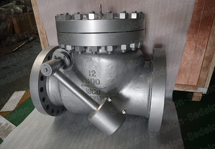
The valve uses swing disc or cushioned tilting-disc designs, with double sealing at the hinge pin to prevent external leakage. The full-bore passage allows pigging operations, and butt weld ends are normally selected because high-pressure flanged connections add weight and create additional leakage paths. Each valve is shell-tested at 1.5 times rated pressure and seat-tested according to API 598, with high-pressure gas testing and EN 10204 3.1/3.2 certificates available.
Main steam and hot reheat lines in supercritical and ultra-supercritical power plantsUsed for Class 1500–2500 service at 540–600 °C, where the pressure-seal bonnet maintains reliable sealing during repeated start-up cycles.
Hydrocracking and hydrotreating unitsSuitable for Class 900–2500 hydrogen-rich gas and hot oil services where bolted bonnet joints require frequent monitoring during thermal cycling.
Ammonia and methanol synthesis loopsApplied in sustained high-pressure systems where increasing line pressure improves sealing performance without hot re-torquing.
High-pressure water and gas injection systemsUsed at injection pump discharge lines where welded connections provide long-term leak prevention.
Supercritical boiler feedwater and high-pressure descaling systemsTilting-disc designs help reduce water hammer during rapid flow changes.
High-pressure steam header isolationThe pressure-seal bonnet reduces long-term stud relaxation and creep leakage under hot steam conditions.
LDPE high-pressure reactor loopsSelected for Class 2500 and above applications where pressure-seal bonnet designs are commonly required.
Bonnet selection:Choose pressure-seal bonnets for Class 900 and above services, especially where high pressure, thermal cycling, or continuous high-temperature operation exists. For lower pressure applications below Class 600, conventional bolted bonnet designs are generally sufficient.
Body and seal ring selection:Choose WCB or A105 for general high-pressure service below approximately 425 °C. Select WC6 for hot steam and hydrogen service, WC9 for main steam applications around 540–590 °C, and C5 or C12A for ultra-supercritical steam systems. Seal rings follow the same temperature selection logic: soft iron or low-carbon steel below 425 °C, stainless steel between 425–550 °C, and silver-plated Inconel above 550 °C.
Disc and end connection selection:Select swing discs for general applications and tilting-disc or slow-closing designs where water hammer is a concern. Butt weld ends according to ASME B16.25 are preferred above Class 900 because heavy flanged connections increase weight and introduce additional leakage paths. RTJ flanged ends can be selected where valve removal for inspection is required.
Additional requirements:Options include API 607 fire-safe design, ISO 15848 low-emission construction, bypass systems for pressure balancing and torque reduction, gear or powered actuation, and EN 10204 3.2 third-party material certification.
At the 1000 MW ultra-supercritical power unit of Zhejiang Energy Jiahua in China, conventional bolted bonnet check valves experienced steam leakage caused by bolt relaxation under frequent thermal cycling and deep load regulation operation. The unit required valves capable of maintaining sealing integrity during repeated start-up, shutdown, and load adjustment conditions. Flowork supplied NPS 10–16, Class 2500 pressure seal check valves featuring A182 F91 heat-resistant steel forged bodies, pressure-energized sealing bonnets, hydraulically damped swing discs, and butt weld ends. The valves were tested according to API 598 requirements with Zhejiang Special Equipment Inspection Institute witness inspection. Since commissioning in 2022, the valves have operated for three years without bonnet leakage, supporting stable unit operation with availability maintained at 99.2%.
Q: Why does a pressure-seal bonnet not leak?A: The sealing force comes from line pressure itself. Pressure pushes the bonnet against the seal ring, increasing the sealing force as operating pressure rises. The compression bolts only provide the initial cold seal.
Q: Why may a pressure-seal valve show brief leakage during cold start-up?A: During warm-up, different expansion rates between the body and bonnet may temporarily affect the initial seal. Once the valve reaches operating temperature and pressure, the seal ring seats tighter. Hot re-torquing is not required.
Q: Can pressure seal check valves use flanged ends?A: Yes, but butt weld ends are normally recommended above Class 900 because Class 1500–2500 flanges become heavy and introduce additional leakage paths. RTJ flanged ends are selected when valve removal for inspection is required.
Q: Why should the top bolts not be re-torqued during operation?A: The top bolts only provide the initial cold preload. The actual sealing force comes from line pressure during operation. Hot re-torquing may load the bonnet unevenly and damage the seal ring.
Q: Does the seal ring need replacement?A: The seal ring should be inspected during overhaul or whenever the valve is opened. After long high-temperature service, replacement is recommended if galling or indentation is found. Matched spare seal rings can be supplied according to body material and temperature class.
Class1500
Pressure Seal Check Valve

| NPS | in | 2 | 2 1/2 | 3 | 4 | 5 | 6 | 8 | 10 | 12 | 14 | 16 |
| d | mm | 47 | 57 | 70 | 92 | 111 | 136 | 178 | 222 | 263 | 289 | 330 |
| L(RF) | mm | 368 | 419 | 470 | 546 | 673 | 705 | 832 | 991 | 1130 | 1257 | 1384 |
| L(BW) | mm | 368 | 419 | 470 | 546 | 673 | 705 | 832 | 991 | 1130 | 1257 | 1384 |
| L(RTJ) | mm | 371 | 422 | 473 | 549 | 676 | 711 | 841 | 1000 | 1146 | 1276 | 1407 |
| d1 | mm | 92 | 105 | 127 | 157 | 186 | 216 | 270 | 324 | 381 | 413 | 470 |
| d2 | mm | 165 | 190.5 | 203.2 | 241.3 | 292.1 | 317.5 | 393.7 | 482.6 | 571.5 | 635 | 704.8 |
| D | mm | 216 | 244 | 267 | 311 | 375 | 394 | 483 | 585 | 675 | 750 | 825 |
| b | mm | 38.5 | 41.5 | 48 | 54 | 73.5 | 83 | 92.9 | 108 | 124 | 133.5 | 146.5 |
| n-Фd | mm | 8-26 | 8-29 | 8-32 | 8-35 | 8-42 | 12-39 | 12-45 | 12-51 | 16-54 | 16-61 | 16-67 |
| H | mm | 210 | 240 | 303 | 340 | 380 | 430 | 500 | 590 | 660 | 710 | 820 |

| NPS | in | 2 | 2 1/2 | 3 | 4 | 5 | 6 | 8 | 10 | 12 |
| d | mm | 38 | 47 | 57 | 73 | 92 | 111 | 146 | 184 | 219 |
| L(RF) | mm | 451 | 508 | 578 | 673 | 794 | 914 | 1022 | 1270 | 1422 |
| L(BW) | mm | 451 | 508 | 578 | 673 | 794 | 914 | 1022 | 1270 | 1422 |
| L(RTJ) | mm | 454 | 514 | 584 | 683 | 807 | 927 | 1038 | 1292 | 1445 |
| d1 | mm | 92 | 105 | 127 | 157 | 186 | 216 | 270 | 324 | 381 |
| d2 | mm | 171.4 | 196.8 | 228.6 | 273 | 323.8 | 368.3 | 438.1 | 539.7 | 619.1 |
| D | mm | 235 | 267 | 305 | 356 | 419 | 483 | 550 | 675 | 760 |
| b | mm | 51 | 57.5 | 67 | 76.5 | 92.5 | 108 | 127 | 165.5 | 184.5 |
| n-Фd | mm | 8-29 | 8-32 | 8-35 | 8-42 | 8-48 | 8-54 | 12-54 | 12-67 | 12-74 |
| H | mm | 230 | 260 | 330 | 370 | 410 | 460 | 530 | 620 | 690 |
API Trim NO.
Table
|
No |
Seat |
Gate、disc 、ball or body |
Stem |
No |
Seat |
Gate、disc 、ball or body |
Stem | |
| 01 | 13Cr | 13Cr | 13Cr | 31 | STELLITE | 321SS | 321SS | |
| 02 | 304SS | 304SS | 304SS | 32 | STELLITE | STELLITE | 321SS | |
| 03 | 310SS | 310SS | 310SS | 33 | 347SS | 347SS | 347SS | |
| 04 | HARD 13Cr | HARD 13Cr | 13Cr | 34 | STELLITE | 347SS | 347SS | |
| 05 | STELLITE | STELLITE | 13Cr | 35 | NICKEL ALLOY | 13Cr | 13Cr | |
| 06 | Cu-Ni | 13Cr | 13Cr | 36 | A105/PTFE | A105+ENP | A105+ENP | |
| 07 | 13Cr | HARD 13Cr | 13Cr | 37 | A105/PTFE | WCB+ENP | A105+ENP | |
| 08 | STELLITE | 13Cr | 13Cr | 38 | 13Cr/PTFE | 13Cr | 13Cr | |
| 09 | Cu-Ni | Cu-Ni | Cu-Ni | 39 | 304SS/PTFE | 304SS | 304SS | |
| 10 | 316SS | 316SS | 316SS | 40 | 316SS/PTFE | 316SS | 316SS | |
| 11 | Cu-Ni | STELLITE | Cu-Ni | 41 | A105/RPTFE | A105+ENP | A105+ENP | |
| 12 | STELLITE | 316SS | 316SS | 42 | A105/RPTFE | WCB+ENP | A105+ENP | |
| 13 | ALLOY 20 | ALLOY 20 | ALLOY 20 | 43 | 13Cr/RPTFE | 13Cr | 13Cr | |
| 14 | STELLITE | ALLOY 20 | ALLOY 20 | 44 | 304SS/RPTFE | 304SS | 304SS | |
| 15 | STELLITE | STELLITE | 304SS | 45 | 316SS/RPTFE | 316SS | 316SS | |
| 16 | STELLITE | STELLITE | 316SS | 46 | A105/NYLON | A105+ENP | A105+ENP | |
| 17 | STELLITE | STELLITE | 347SS | 47 | A105/NYLON | WCB+ENP | A105+ENP | |
| 18 | STELLITE | STELLITE | ALLOY 20 | 48 | A105/NYLON | 304SS | 304SS | |
| 19 | MONEL | MONEL | MONEL | 49 | A105/NYLON | 316SS | 316SS | |
| 20 | BRONZE | BRONZE | 13Cr | 50 | 13Cr/NYLON | 13Cr | 13Cr | |
| 21 | HASTELLOY B | HASTELLOY B | HASTELLOY B | 51 | 304SS/NYLON | 304SS | 304SS | |
| 22 |
| HASTELLOY C | HASTELLOY C | 52 | 316SS/NYLON | 316SS | 316SS | |
| 23 | STELLITE | 304SS | 304SS | 53 | A105/PEEK | A105+ENP | A105+ENP | |
| 24 | 304LSS | 304LSS | 304LSS | 54 | A105/PEEK | WCB+ENP | A105+ENP | |
| 25 | STELLITE | 304LSS | 304LSS | 55 | 13Cr/PEEK | 13Cr | 13Cr | |
| 26 | STELLITE | STELLITE | 304LSS | 56 | 304SS/PEEK | 304SS | 304SS | |
| 27 | 316LSS | 316LSS | 316LSS | 57 | 316SS/PEEK | 316SS | 316SS | |
| 28 | STELLITE | 316LSS | 316LSS |
|
|
|
|
|
| 29 | STELLITE | STELLITE | 316LSS |
|
|
| ||
| 30 | 321SS | 321SS | 321SS |
|
|
|
| |
Note:please indicate it directly in the
order for the internal part’smaterial uncovered in the table


 Optimized by Seraphinite Accelerator