



 Skip to content

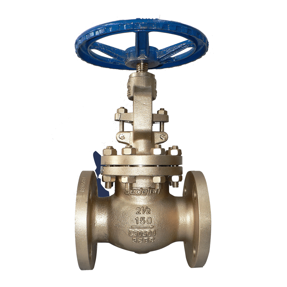
The fundamental difference between a globe valve and a gate valve lies in the former’s ability to throttle flow, a capability determined by its structure. A gate valve consists of a flat plate that moves vertically and can only be in one of two positions: fully open or fully closed. In a globe valve, the disc moves vertically along the seat orifice and can create stable throttling at any point during its stroke; therefore, it is used for flow regulation, pipeline balancing, and sampling control.
The trade-off is pressure drop. The flow path of a globe valve forms an S-shaped double bend, causing the medium to change direction twice within the valve body; the pressure drop is approximately several to ten times that of a gate valve of the same nominal diameter. Pump power consumption must be calculated during selection—on high-flow cooling water lines, using a globe valve as a shut-off valve can result in long-term energy losses; in such cases, a gate valve or butterfly valve should be used instead.
There are several other points in the European standard system that must not be confused. DIN 3202 classifies valves into series based on structure; F2 belongs to the globe valve series, while F7 belongs to the gate valve series. For the same nominal diameter, F2 is shorter than F7, so when substituting a globe valve for a gate valve, the flange-to-flange distance will not align. Design and manufacturing follow EN 13709/DIN 3356, while flanges comply with EN 1092-1/DIN 2545. The bore center circle and number of bolts increase with PN, making them incompatible with ANSI B16.5. Material grades are classified by flow velocity: C95800 for flowing seawater, C95500 for sand-laden sections, and C95600 for low-velocity sections. Bronze has approximately half the hardness of steel; even though throttling is permitted in globe valves, long-term erosion at small opening angles can still damage the conical seat surface. It is recommended to maintain the minimum opening at 20% or higher; for high-velocity conditions, C95500 should be selected as the preferred grade.
Valve Type Selection: Select a globe valve for applications requiring flow regulation, pipeline balancing, or control of sampling flow; select a gate valve for applications requiring only fully open or fully closed operation where pressure drop is a concern. The two valve types are not interchangeable.
Pressure Drop Calculation: Globe valves have an S-shaped flow path, resulting in a pressure drop that is several to ten times greater than that of a gate valve of the same diameter. On high-flow pipelines, calculate pump power consumption to ensure that long-term energy consumption remains acceptable.
Dimension Verification: Face-to-face dimensions comply with EN 558-1/DIN 3202 F2 (globe valve series); flange dimensions comply with EN 1092-1/DIN 2545. The F7 (gate valve series) has a longer face-to-face dimension for the same nominal diameter and is not interchangeable.
Materials and Opening: C95800 for flowing seawater, C95500 for sand-laden sections, and C95600 for low-velocity sections; bronze is relatively soft, so for long-term throttling, the minimum opening should not be less than 20%; C95500 is preferred for high-velocity conditions.
Optional Features: Gear operation, extended stem, locking device, and EN 10204 3.1 material certificate.
Q: Can a DIN globe valve replace a DIN gate valve?
Functionally, no; in terms of length, it may not work either. Globe valves can throttle flow, while gate valves can only be fully open or fully closed. For face-to-face measurements, globe valves are F2 and gate valves are F7; for the same nominal diameter, the F2 globe valve is shorter, so the flange-to-flange distance won’t match when substituting one for the other.
Q: Why is the pressure drop in a globe valve greater than in a gate valve?
The flow path of a globe valve is an S-shaped double-bend; the medium changes direction twice within the valve body, resulting in a pressure drop that is several to ten times greater than that of a gate valve of the same nominal diameter. Using a globe valve for shutoff on high-flow pipelines will cause long-term energy losses; a gate valve or butterfly valve should be selected instead.
Q: Can a bronze globe valve be used for long-term throttling at a small opening?
Throttling is possible, but since bronze is about half as hard as steel, high-velocity media at a very small opening over a long period can erode the cone surface. It is recommended that the minimum opening be no less than 20 percent; for high-velocity flow or sand-laden conditions, C95500 should be the preferred choice.
For the F-110-class frigate project at Navantia Shipyard in Spain, a total of 380 DN15–DN50 PN16 DIN bronze globe valves were procured for flow regulation in seawater cooling, fresh water supply, and fire protection piping systems. The valves are made of C95800 aluminum bronze and come with LR classification society certification. After three years of operation, there have been zero cases of cavitation-induced leakage or erosion damage to the valve discs, and the flow control accuracy has met design requirements. As a result, an additional order for 260 units was placed for subsequent frigates of the same class.
PN16 BronzeDIN GolbeValve
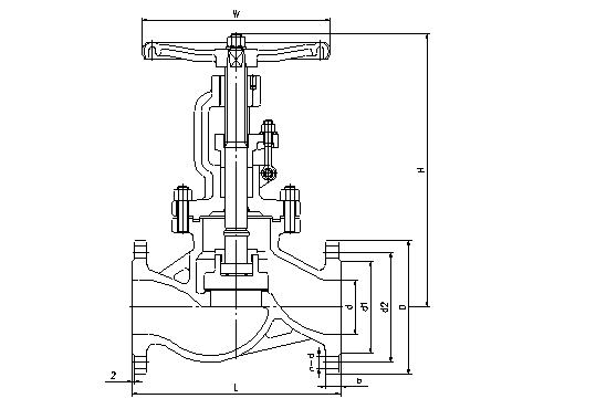
| DN |
| 50 | 65 | 80 | 100 | 125 | 150 | 200 | 250 | 300 | 350 | 400 |
| d | mm | 50 | 63 | 76 | 100 | 125 | 150 | 200 | 250 | 300 | 336 | 387 |
| L(RF) | mm | 230 | 290 | 310 | 350 | 400 | 480 | 600 | 730 | 850 | 980 | 1100 |
| d1 | mm | 102 | 122 | 138 | 158 | 188 | 212 | 268 | 320 | 378 | 438 | 490 |
| d2 | mm | 125 | 145 | 160 | 180 | 210 | 240 | 295 | 355 | 410 | 470 | 525 |
| D | mm | 165 | 185 | 200 | 220 | 250 | 285 | 340 | 405 | 460 | 520 | 580 |
| b | mm | 18 | 18 | 20 | 20 | 22 | 22 | 24 | 26 | 28 | 30 | 32 |
| n-Фd | mm | 4-18 | 8-18 | 8-18 | 8-18 | 8-18 | 8-22 | 12-22 | 12-26 | 12-26 | 16-26 | 16-30 |
| H | mm | 305 | 354 | 402 | 437 | 496 | 541 | 699 | 815 | 914 | 1189 | 1350 |
| W | mm | 200 | 200 | 250 | 250 | 300 | 350 | 400 | 450 | 500 | 550 | 600 |
PN25 BronzeDIN Golbe
Valve

| DN |
| 50 | 65 | 80 | 100 | 125 | 150 | 200 | 250 | 300 | 350 | 400 |
| d | mm | 50 | 63 | 76 | 100 | 125 | 150 | 200 | 250 | 300 | 336 | 387 |
| L(RF) | mm | 230 | 290 | 310 | 350 | 400 | 480 | 600 | 730 | 850 | 980 | 1100 |
| d1 | mm | 102 | 122 | 138 | 162 | 188 | 218 | 278 | 335 | 395 | 450 | 505 |
| d2 | mm | 125 | 145 | 160 | 190 | 220 | 250 | 310 | 370 | 430 | 490 | 550 |
| D | mm | 165 | 185 | 200 | 235 | 270 | 300 | 360 | 425 | 485 | 555 | 620 |
| b | mm | 20 | 22 | 24 | 24 | 28 | 28 | 30 | 32 | 34 | 38 | 40 |
| n-Фd | mm | 4-18 | 8-18 | 8-18 | 8-22 | 8-26 | 8-26 | 12-26 | 12-30 | 16-30 | 16-33 | 16-36 |
| H | mm | 325 | 363 | 415 | 453 | 505 | 556 | 744 | 864 | 948 | 1269 | 1450 |
| W | mm | 200 | 200 | 250 | 300 | 350 | 400 | 450 | 500 | 550 | 600 | 600 |
PN40 BronzeDIN GolbeValve
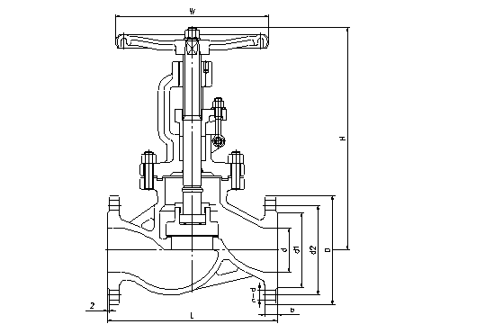
| DN |
| 50 | 65 | 80 | 100 | 125 | 150 | 200 | 250 | 300 | 350 | 400 |
| d | mm | 50 | 63 | 76 | 100 | 125 | 150 | 200 | 250 | 300 | 336 | 387 |
| L(RF) | mm | 230 | 290 | 310 | 350 | 400 | 480 | 600 | 730 | 850 | 980 | 1100 |
| d1 | mm | 102 | 122 | 138 | 162 | 188 | 218 | 285 | 345 | 410 | 465 | 535 |
| d2 | mm | 125 | 145 | 160 | 190 | 220 | 250 | 320 | 385 | 450 | 510 | 585 |
| D | mm | 165 | 185 | 200 | 235 | 270 | 300 | 375 | 460 | 515 | 580 | 660 |
| b | mm | 20 | 22 | 24 | 24 | 28 | 28 | 34 | 38 | 42 | 46 | 50 |
| n-Фd | mm | 4-18 | 8-18 | 8-18 | 8-22 | 8-26 | 8-26 | 12-30 | 12-33 | 16-33 | 16-36 | 16-39 |
| H | mm | 325 | 370 | 430 | 480 | 532 | 589 | 783 | 888 | 965 | 1285 | 1512 |
| W | mm | 200 | 200 | 250 | 300 | 350 | 400 | 450 | 500 | 550 | 600 | 600 |
PN63 BronzeDIN GolbeValve
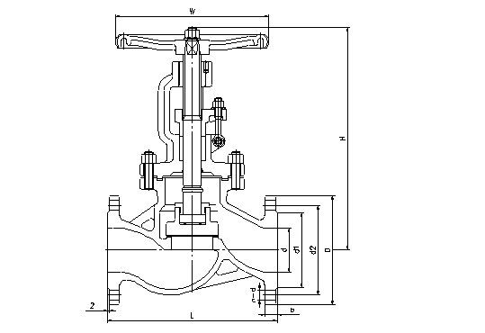
| DN |
| 50 | 65 | 80 | 100 | 125 | 150 | 200 | 250 | 300 | 350 | 400 |
| d | mm | 50 | 63 | 76 | 100 | 125 | 150 | 200 | 250 | 300 | 336 | 387 |
| L(RF) | mm | 300 | 340 | 380 | 430 | 500 | 550 | 650 | 775 | 900 | 1025 | 1150 |
| d1 | mm | 102 | 122 | 138 | 162 | 188 | 218 | 285 | 345 | 410 | 465 | 535 |
| d2 | mm | 135 | 160 | 170 | 200 | 240 | 280 | 345 | 400 | 460 | 525 | 585 |
| D | mm | 180 | 205 | 215 | 250 | 295 | 345 | 415 | 470 | 530 | 600 | 670 |
| b | mm | 26 | 26 | 28 | 30 | 34 | 36 | 42 | 48 | 52 | 56 | 60 |
| n-Фd | mm | 4-22 | 8-22 | 8-22 | 8-28 | 8-30 | 8-33 | 12-36 | 12-36 | 16-36 | 16-39 | 16-42 |
| H | mm | 305 | 354 | 402 | 437 | 496 | 541 | 699 | 815 | 914 | 1189 | 1350 |
| W | mm | 200 | 200 | 250 | 250 | 300 | 350 | 400 | 450 | 500 | 550 | 600 |
|
|
|
|
|
|
|
|
|
|
|
|
|
|
 Optimized by Seraphinite Accelerator