



 Skip to content

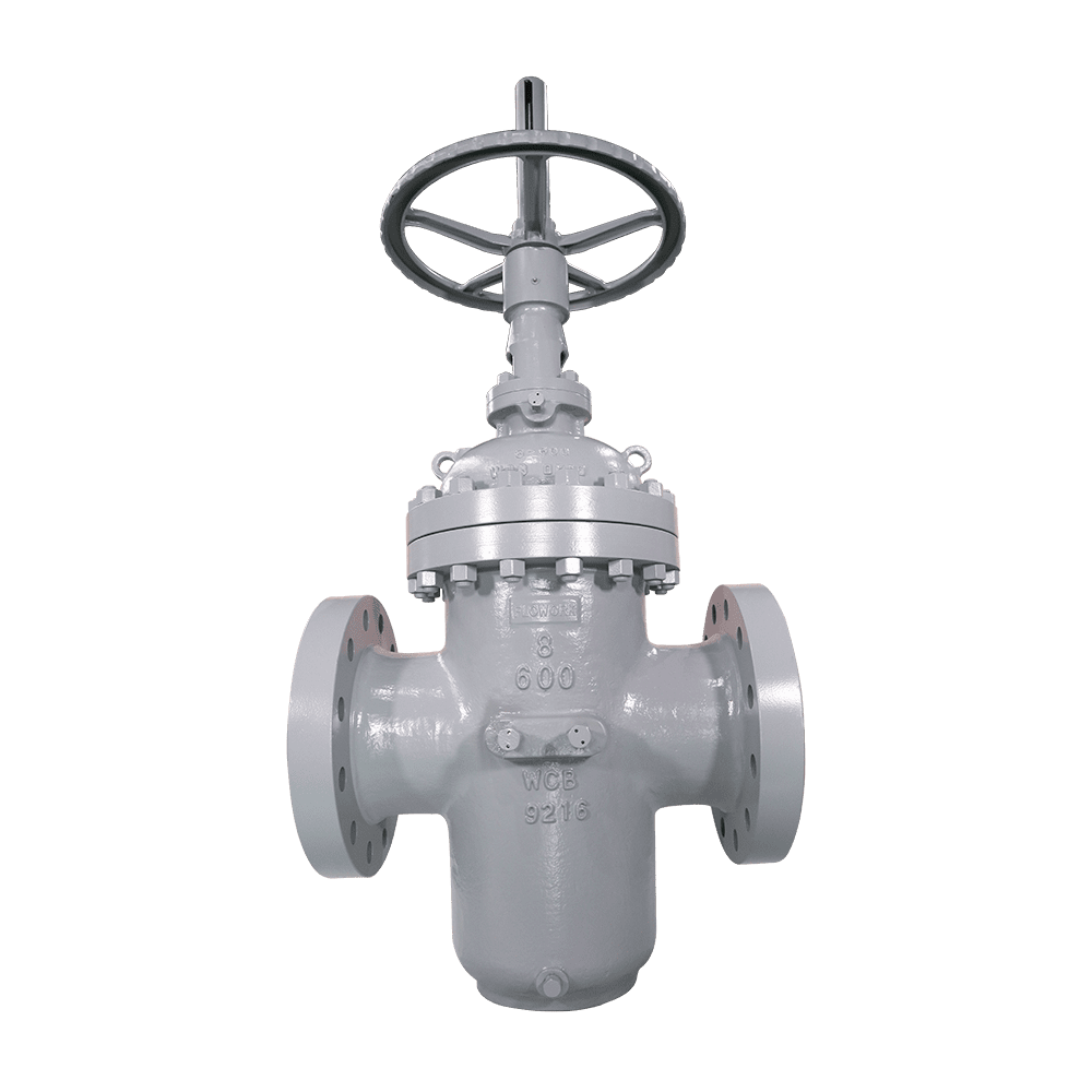
The primary difference between a slab gate valve and a wedge gate valve is the gate configuration, and this difference directly determines whether the valve is suitable for pipelines requiring pigging. A wedge gate has inclined sealing surfaces and relies on wedging force to achieve sealing. While this provides high sealing contact pressure, it also makes the valve sensitive to solid particles. A slab gate valve uses a flat parallel gate with a set of floating seats on each side. As the gate moves downward, it pushes the two seats apart. Sealing is achieved as the seats self-energize against the gate under medium pressure and spring force. Because there are no wedging surfaces on the back of the gate, debris is not compacted between the sealing surfaces to form indentations.
The slab design uses a full-bore flow passage. When the valve is fully open, the internal diameter matches that of the pipeline, allowing pigs to pass smoothly. This is a mandatory requirement on long-distance crude oil and natural gas transmission pipelines.
The floating seats also provide a practical advantage: the two seats can operate independently to provide bidirectional sealing, while the body cavity can be independently bled. This makes the design suitable for metering and isolation points where online verification of valve leakage is required.
Emergency sealant injection fittings are provided at the valve body and seats. In the event of minor leakage at the sealing surfaces, sealant can be injected for temporary sealing without shutting down the pipeline. A pressure relief passage is provided between the seats and valve body, allowing abnormal cavity pressure to be directed to the low-pressure side.
The trade-off is that the overall height and weight are greater than those of a wedge gate valve of the same size, and debris can accumulate inside the cavity. Care should therefore be taken when selecting this design for media with high solids content. Each valve undergoes shell and sealing tests in accordance with API 598.
Long-distance crude oil and natural gas transmission pipelines: full-bore flow passage allows pigs to pass directly through.
High-pressure oil and gas gathering pipelines: dual floating seats provide bidirectional sealing and accommodate pipeline vibration.
Metering and isolation points: double block and bleed construction allows online verification of valve leakage.
Pipelines in deserts, mountainous regions, and other areas requiring frequent pigging: the slab gate is less sensitive to solid particles, and the sealing surfaces are less prone to indentation.
Storage and transfer facilities and loading pipelines: flow resistance is close to that of a straight pipe when fully open, reducing energy consumption during transportation.
Application: Select a slab gate valve for isolation points requiring pigging or a full-bore, low-resistance flow passage. A wedge gate valve may be considered for normal-temperature, normal-pressure isolation applications where pigging is not required, offering lower cost.
Sealing and pressure relief: For high-pressure, large-bore pipelines, select dual floating seats with a pressure relief passage to direct excessive cavity pressure to the low-pressure side. Select double block and bleed construction where online verification of internal leakage is required.
Emergency maintenance: Confirm that the valve body is equipped with emergency sealant injection fittings. In the event of minor leakage at the sealing surfaces, sealant can be injected for temporary sealing without shutting down the pipeline.
Materials and service media: Use WCB or A105 for general oil and gas service, CF8, CF8M, or F316 for corrosive media, and LCC for low-temperature service. For media with high solids content, the slab design should be selected with caution, with filtration or draining measures provided as required.
Q: How should I choose between a slab gate valve and a wedge gate valve?
A: A slab gate valve uses a flat parallel gate with floating seats, providing a full-bore passage, pigging capability, and lower sensitivity to solid particles. It is suitable for long-distance pipelines and pipelines requiring frequent pigging. A wedge gate valve relies on wedging action, providing high sealing contact pressure but incorporating internal steps that prevent pigging. It is suitable for clean-media isolation applications where pigging is not required.
Q: What should I do if the body cavity pressure rises after the valve is closed?
A: A pressure relief passage is provided between the floating seats and the valve body. When the cavity pressure rises abnormally, the pressure is directed to the low-pressure side. During installation, the pressure relief direction must be confirmed to match the low-pressure side of the pipeline.
Q: Can minor leakage be addressed without shutting down the pipeline?
A: Emergency sealant injection fittings are provided on the valve body. Sealant can be injected in the event of minor leakage to restore temporary sealing performance. However, sealant injection is only an emergency measure; permanent repair requires pipeline isolation followed by maintenance.
The high-pressure oil and gas gathering pipeline of Groupement Berkine at Hassi Berkine in Algeria crosses desert terrain and requires frequent pigging. The original gate valves were unable to accommodate pipeline vibration, resulting in seat damage and internal leakage within 15 months. Each repair required isolation of a 60 km pipeline section and took 40 hours.
Flowork supplied 22 NPS 4–6, Class 2500 slab gate valves featuring A216 WCB valve bodies, dual floating-seat slab gates, tungsten carbide-coated seat sealing surfaces, and full-bore flow passages to meet pigging requirements. The valves were designed in accordance with API 6D and tested in accordance with API 598, with on-site inspection witnessed by the Groupement Berkine quality control department.
Since commissioning in January 2022, the valves have operated continuously for three years with zero internal leakage. Repair-related isolation shutdowns were reduced from twice a year to zero, and pigging operations no longer require valve removal.
| Parameter | Specifications |
| Design Standard | API 6D, ASME B16.34 |
| Size Range | 2” to 48” (DN50 – DN1200) |
| Pressure Class | Class 150 to Class 2500 |
| Body Material | WCB, LCC, CF8, CF8M, A105, F316 |
| Connection | Flanged (RF, RTJ), Butt-Weld (BW) |
| Operation | Manual, Gear, Electric, or Pneumatic Actuator |
Class150 Slab Gate Valve

| NPS | in | 2 | 2 1/2 | 3 | 4 | 5 | 6 | 8 | 10 | 12 | 14 | 16 | 18 | 20 | 24 |
| d | mm | 51 | 64 | 76 | 102 | 127 | 152 | 203 | 254 | 305 | 337 | 387 | 438 | 489 | 591 |
| L(RF) | mm | 178 | 190 | 203 | 229 | 254 | 267 | 292 | 330 | 356 | 381 | 406 | 432 | 457 | 508 |
| L(BW) | mm | 216 | 241 | 283 | 305 | 381 | 403 | 419 | 457 | 502 | 572 | 610 | 660 | 711 | 813 |
| L(RTJ) | mm | 191 | 203 | 216 | 241 | 267 | 279 | 305 | 343 | 368 | 394 | 419 | 445 | 470 | 521 |
| d1 | mm | 92 | 105 | 127 | 157 | 186 | 216 | 270 | 324 | 381 | 413 | 470 | 533 | 584 | 692 |
| d2 | mm | 120.5 | 139.5 | 152.5 | 190.5 | 216 | 241.5 | 298.5 | 362 | 432 | 476 | 540 | 578 | 635 | 749.5 |
| D | mm | 152 | 178 | 190 | 229 | 254 | 279 | 343 | 406 | 483 | 533 | 597 | 635 | 699 | 813 |
| b | mm | 16 | 18 | 19 | 24 | 24 | 26 | 29 | 31 | 32 | 35 | 37 | 40 | 43 | 48 |
| n-Фd | mm | 4-19 | 4-19 | 4-19 | 8-19 | 8-22 | 8-22 | 8-22 | 12-25 | 12-25 | 12-29 | 16-29 | 16-32 | 20-32 | 20-35 |
Class300 Slab Gate Valve

| NPS | in | 2 | 2 1/2 | 3 | 4 | 5 | 6 | 8 | 10 | 12 | 14 | 16 | 18 | 20 | 24 |
| d | mm | 51 | 64 | 76 | 102 | 127 | 152 | 203 | 254 | 305 | 337 | 387 | 432 | 483 | 584 |
| L(RF) | mm | 216 | 241 | 283 | 305 | 381 | 403 | 419 | 457 | 502 | 762 | 838 | 914 | 991 | 1143 |
| L(BW) | mm | 216 | 241 | 283 | 305 | 381 | 403 | 419 | 457 | 502 | 762 | 838 | 914 | 991 | 1143 |
| L(RTJ) | mm | 232 | 257 | 298 | 321 | 397 | 419 | 435 | 473 | 518 | 778 | 854 | 930 | 1010 | 1165 |
| d1 | mm | 92 | 105 | 127 | 157 | 186 | 216 | 270 | 324 | 381 | 413 | 470 | 533 | 584 | 692 |
| d2 | mm | 127 | 149 | 168.5 | 200 | 235 | 270 | 330 | 387.5 | 451 | 514.5 | 571.5 | 628.5 | 686 | 813 |
| D | mm | 165 | 190 | 210 | 254 | 279 | 318 | 381 | 445 | 521 | 584 | 648 | 711 | 775 | 914 |
| b | mm | 23 | 26 | 29 | 32 | 35 | 37 | 42 | 48 | 51 | 54 | 58 | 61 | 64 | 70 |
| n-Фd | mm | 8-19 | 8-22 | 8-22 | 8-22 | 8-22 | 12-22 | 12-25 | 16-29 | 16-32 | 20-32 | 20-35 | 24-35 | 24-35 | 24-41 |
Class600 Slab Gate Valve

| NPS | in | 2 | 2 1/2 | 3 | 4 | 5 | 6 | 8 | 10 | 12 | 14 | 16 | 18 | 20 | 24 |
| d | mm | 51 | 64 | 76 | 102 | 127 | 152 | 200 | 248 | 298 | 327 | 375 | 419 | 464 | 559 |
| L(RF) | mm | 292 | 330 | 356 | 432 | 508 | 559 | 660 | 787 | 838 | 889 | 991 | 1092 | 1194 | 1397 |
| L(BW) | mm | 292 | 330 | 356 | 432 | 508 | 559 | 660 | 787 | 838 | 889 | 991 | 1092 | 1194 | 1397 |
| L(RTJ) | mm | 295 | 333 | 359 | 435 | 511 | 562 | 664 | 791 | 841 | 892 | 994 | 1095 | 1200 | 1407 |
| d1 | mm | 92 | 105 | 127 | 157 | 186 | 216 | 270 | 324 | 381 | 413 | 470 | 533 | 584 | 692 |
| d2 | mm | 127 | 149 | 168.5 | 216 | 267 | 292 | 349 | 432 | 489 | 527 | 603 | 654 | 724 | 838 |
| D | mm | 165 | 190 | 210 | 273 | 330 | 356 | 419 | 508 | 559 | 603 | 686 | 743 | 813 | 940 |
| b | mm | 26 | 29 | 32 | 38 | 45 | 48 | 56 | 64 | 67 | 70 | 77 | 83 | 89 | 102 |
| n-Фd | mm | 8-19 | 8-22 | 8-22 | 8-25 | 8-29 | 12-29 | 12-32 | 16-35 | 20-35 | 20-38 | 20-41 | 20-44 | 24-44 | 24-52 |



 Optimized by Seraphinite Accelerator