



 Skip to content

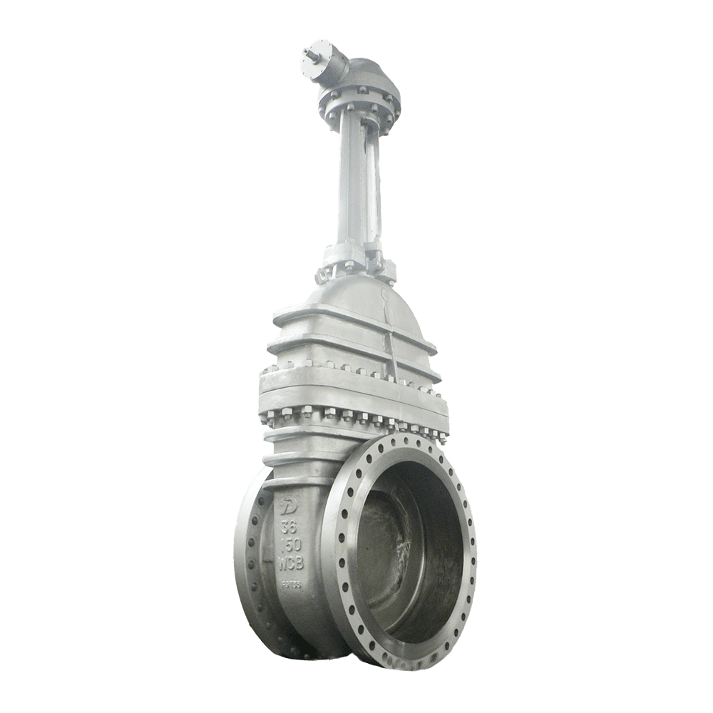
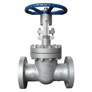
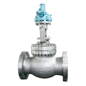
This product features a rising stem resilient wedge gate design. Once the valve size exceeds NPS 30, the weight of a single valve can reach several tons, while the gate travel increases proportionally with valve size. Full-stroke handwheel operation may require several hundred turns. Therefore, large-size gate valves are typically equipped with a bypass valve, gearbox, or electric actuator. Direct handwheel operation is not recommended for large-size, high-pressure gate valves.
The valve body is made of A216 WCB cast steel. Thick-wall castings are susceptible to defects such as shrinkage cavities and inclusions during casting, so critical pressure-retaining areas require individual magnetic particle or ultrasonic examination. The sealing surfaces are hardfaced with Stellite 21 cobalt-based hard alloy, with a hardness of no less than HRC 40. This allows the valve to maintain sealing performance under long-term erosive service with solid particles, such as sand-containing crude oil, and prevents premature failure of soft sealing surfaces due to particle erosion.
The stem is made of nitrided stainless steel, providing high surface hardness as well as wear and galling resistance. The packing consists of flexible graphite reinforced with stainless steel wire to meet the sealing requirements of high-temperature service. Each valve undergoes shell strength and seat leakage testing in accordance with API 598 prior to shipment. Large-size valves require dedicated pressure test equipment, with the shell test pressure set at 1.5 times the nominal pressure and the holding time correspondingly extended as valve size increases. During installation, particular attention must be paid to pipeline alignment to prevent additional piping loads from acting on the valve body and causing deformation or leakage.
Large-diameter isolation on crude oil transmission pipelines at initial, intermediate, and terminal pump stations, NPS 24 and above
Inlet and outlet isolation for tank farms and commercial crude oil storage facilities
Inlet and return isolation on large-diameter circulating cooling water pipelines in coastal and nuclear power plants
Isolation on main outlet and intake pipelines at large wastewater treatment plants
Mainline isolation for long-distance water transmission projects
Large-diameter feedstock oil and refined product pipelines in coal chemical and refining/petrochemical plants
For valve sizes of NPS 16 and above with pressure ratings of Class 300 and above, a gearbox or electric actuator must be provided. The operating torque for direct handwheel operation is excessive and may prevent normal opening and closing.
For services containing sand or solid particles, the sealing surfaces must be hardfaced with Stellite alloy. Copper alloys or soft sealing should not be used, as the sealing surfaces may be rapidly eroded and fail.
Large-size gate valves should be equipped with a bypass valve. Open the bypass valve first to equalize the pressure differential across the main valve, which can significantly reduce opening torque and prevent the gate from being locked against the seat by high pressure.
For electric-operated gate valves, specify the stem torque, travel, power supply voltage, and control requirements. The actuator thrust should have sufficient margin. For outdoor installation, an outdoor-duty actuator protective cover should be provided.
Hunt Oil’s crude oil export pipeline in the Kurdistan Region of Iraq (NPS 36, Class 300) transports high-sulfur crude oil containing 3.5% sulfur and trace amounts of sand. The sealing surfaces of the original cast steel gate valves developed internal leakage after only 15 months of long-term erosion from sand-containing crude oil. Each maintenance shutdown required 36 hours of pipeline downtime, resulting in an estimated loss of approximately 55,000 tons of export volume.
We supplied 14 NPS 30 to NPS 36, Class 300 large-size gate valves featuring A216 WCB valve bodies, rising stem resilient wedge gates, Stellite 21 hardfaced sealing surfaces, and RF flanged ends. The valves were designed in accordance with API 600 and subjected to shell and seat leakage testing in accordance with API 598, with inspection witnessed by the owner’s representatives. Since commissioning in March 2022, the valves have operated continuously for 3 years with zero internal leakage. The maintenance interval was extended from 15 months to more than 4 years, unplanned pipeline shutdowns were reduced from two per year to zero, and crude oil export capacity has remained consistently at the design level.
Q1: Why should the bypass valve be opened before opening the main valve?
Under large-size, high-pressure conditions, the pressure differential across the valve can reach several MPa. Directly opening the gate requires extremely high operating torque and may damage the sealing surfaces. Opening the bypass valve first to equalize the pressure differential makes operation easier and protects the sealing surfaces.
Q2: Can the handwheel or electric actuator continue operating after the valve reaches the fully open position?
No. Once the valve reaches its travel limit, operation must stop. Do not continue applying force, as this may bend the stem or damage the gate or stem nut. For electric-operated valves, the travel limit and torque protection must be properly adjusted.
Q3: How should leakage at the valve body-to-bonnet connection be handled during operation?
First, evenly tighten the bonnet bolts. If leakage persists, depressurize and cool the valve before replacing the bonnet gasket. The bolts must be tightened evenly in a diagonal sequence to prevent flange distortion.
Q4: What should be considered when installing a large-size valve?
Do not attach lifting slings to the handwheel or stem during lifting. The valve body lifting lugs must be used. The pipeline must be properly aligned during installation, and forced pipe alignment must not be used, as this can transfer piping stresses to the valve body.
Class150 Big Size Gate Valve
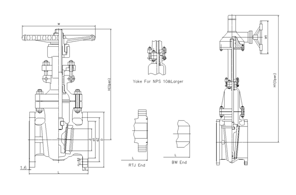
| NPS | in | 2 | 2 1/2 | 3 | 4 | 5 | 6 | 8 | 10 | 12 | 14 | 16 | 18 | 20 | 24 |
| d | mm | 51 | 64 | 76 | 102 | 127 | 152 | 203 | 254 | 305 | 337 | 387 | 438 | 489 | 591 |
| L(RF) | mm | 178 | 190 | 203 | 229 | 254 | 267 | 292 | 330 | 356 | 381 | 406 | 432 | 457 | 508 |
| L(BW) | mm | 216 | 241 | 283 | 305 | 381 | 403 | 419 | 457 | 502 | 572 | 610 | 660 | 711 | 813 |
| L(RTJ) | mm | 191 | 203 | 216 | 241 | 267 | 279 | 305 | 343 | 368 | 394 | 419 | 445 | 470 | 521 |
| d1 | mm | 92 | 105 | 127 | 157 | 186 | 216 | 270 | 324 | 381 | 413 | 470 | 533 | 584 | 692 |
| d2 | mm | 120.5 | 139.5 | 152.5 | 190.5 | 216 | 241.5 | 298.5 | 362 | 432 | 476 | 540 | 578 | 635 | 749.5 |
| D | mm | 152 | 178 | 190 | 229 | 254 | 279 | 343 | 406 | 483 | 533 | 597 | 635 | 699 | 813 |
| b | mm | 16 | 18 | 19 | 24 | 24 | 26 | 29 | 31 | 32 | 35 | 37 | 40 | 43 | 48 |
| n-Фd | mm | 4-19 | 4-19 | 4-19 | 8-19 | 8-22 | 8-22 | 8-22 | 12-25 | 12-25 | 12-29 | 16-29 | 16-32 | 20-32 | 20-35 |
| H | mm | 400 | 435 | 515 | 595 | 725 | 780 | 975 | 1150 | 1380 | 1545 | 1733 | 1915 | 2122 | 2520 |
| H1 | mm | 820 | 1020 | 1200 | 1430 | 1580 | 1780 | 1990 | 2220 | 2600 | |||||
| W | mm | 200 | 200 | 250 | 280 | 280 | 300 | 350 | 400 | 450 | 500 | 500 | 500 | 600 | 600 |
| W1 | mm | 310 | 310 | 310 | 310 | 310 | 460 | 460 | 460 | 460 |
Class300 Big Size Gate Valve
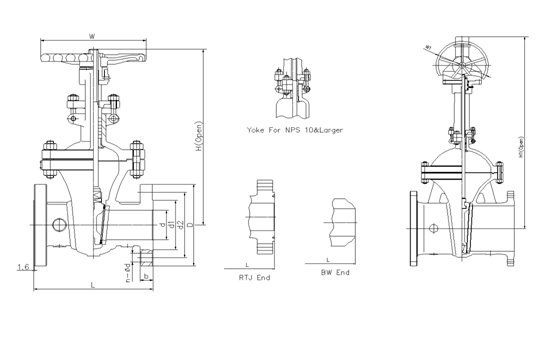
| NPS | in | 2 | 2 1/2 | 3 | 4 | 5 | 6 | 8 | 10 | 12 | 14 | 16 | 18 | 20 | 24 |
| d | mm | 51 | 64 | 76 | 102 | 127 | 152 | 203 | 254 | 305 | 337 | 387 | 432 | 483 | 584 |
| L(RF) | mm | 216 | 241 | 283 | 305 | 381 | 403 | 419 | 457 | 502 | 762 | 838 | 914 | 991 | 1143 |
| L(BW) | mm | 216 | 241 | 283 | 305 | 381 | 403 | 419 | 457 | 502 | 762 | 838 | 914 | 991 | 1143 |
| L(RTJ) | mm | 232 | 257 | 298 | 321 | 397 | 419 | 435 | 473 | 518 | 778 | 854 | 930 | 1010 | 1165 |
| d1 | mm | 92 | 105 | 127 | 157 | 186 | 216 | 270 | 324 | 381 | 413 | 470 | 533 | 584 | 692 |
| d2 | mm | 127 | 149 | 168.5 | 200 | 235 | 270 | 330 | 387.5 | 451 | 514.5 | 571.5 | 628.5 | 686 | 813 |
| D | mm | 165 | 190 | 210 | 254 | 279 | 318 | 381 | 445 | 521 | 584 | 648 | 711 | 775 | 914 |
| b | mm | 23 | 26 | 29 | 32 | 35 | 37 | 42 | 48 | 51 | 54 | 58 | 61 | 64 | 70 |
| n-Фd | mm | 8-19 | 8-22 | 8-22 | 8-22 | 8-22 | 12-22 | 12-25 | 16-29 | 16-32 | 20-32 | 20-35 | 24-35 | 24-35 | 24-41 |
| H | mm | 420 | 446 | 537 | 619 | 722 | 806 | 1000 | 1240 | 1425 | 1585 | 1790 | 1960 | 2158 | 2576 |
| H1 | mm | 650 | 750 | 835 | 1030 | 1280 | 1460 | 1620 | 1830 | 2000 | 2220 | 2620 | |||
| W | mm | 200 | 200 | 250 | 280 | 300 | 350 | 400 | 450 | 500 | 500 | 600 | 650 | 750 | 900 |
| W1 | mm | 310 | 310 | 310 | 310 | 310 | 310 | 460 | 460 | 460 | 460 | 600 |
Class600 Big Size Gate Valve
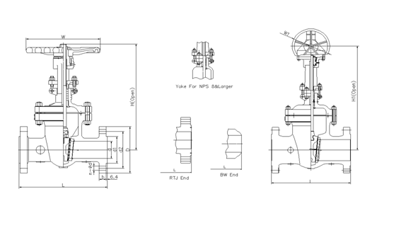
| NPS | in | 2 | 2 1/2 | 3 | 4 | 5 | 6 | 8 | 10 | 12 | 14 | 16 | 18 | 20 | 24 |
| d | mm | 51 | 64 | 76 | 102 | 127 | 152 | 200 | 248 | 298 | 327 | 375 | 419 | 464 | 559 |
| L(RF) | mm | 292 | 330 | 356 | 432 | 508 | 559 | 660 | 787 | 838 | 889 | 991 | 1092 | 1194 | 1397 |
| L(BW) | mm | 292 | 330 | 356 | 432 | 508 | 559 | 660 | 787 | 838 | 889 | 991 | 1092 | 1194 | 1397 |
| L(RTJ) | mm | 295 | 333 | 359 | 435 | 511 | 562 | 664 | 791 | 841 | 892 | 994 | 1095 | 1200 | 1407 |
| d1 | mm | 92 | 105 | 127 | 157 | 186 | 216 | 270 | 324 | 381 | 413 | 470 | 533 | 584 | 692 |
| d2 | mm | 127 | 149 | 168.5 | 216 | 267 | 292 | 349 | 432 | 489 | 527 | 603 | 654 | 724 | 838 |
| D | mm | 165 | 190 | 210 | 273 | 330 | 356 | 419 | 508 | 559 | 603 | 686 | 743 | 813 | 940 |
| b | mm | 26 | 29 | 32 | 38 | 45 | 48 | 56 | 64 | 67 | 70 | 77 | 83 | 89 | 102 |
| n-Фd | mm | 8-19 | 8-22 | 8-22 | 8-25 | 8-29 | 12-29 | 12-32 | 16-35 | 20-35 | 20-38 | 20-41 | 20-44 | 24-44 | 24-52 |
| H | mm | 444 | 500 | 558 | 665 | 760 | 868 | 1073 | 1263 | 1600 | 1705 | 1835 | |||
| H1 | mm | 585 | 695 | 790 | 900 | 1110 | 1300 | 1650 | 1750 | 1900 | 2020 | 2172 | 2650 | ||
| W | mm | 200 | 250 | 280 | 300 | 350 | 450 | 500 | 650 | 700 | 900 | 900 | |||
| W1 | mm | 310 | 310 | 310 | 310 | 310 | 460 | 460 | 460 | 460 | 600 | 600 | 600 |
Class900 Big Size Gate Valve
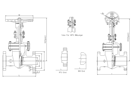
| NPS | in | 2 | 2 1/2 | 3 | 4 | 5 | 6 | 8 | 10 | 12 | 14 | 16 | 18 | 20 | 24 |
| d | mm | 47 | 57 | 73 | 98 | 121 | 146 | 190 | 234 | 282 | 311 | 354 | 400 | 444 | 533 |
| L(RF) | mm | 368 | 419 | 381 | 457 | 559 | 610 | 737 | 838 | 965 | 1029 | 1130 | 1219 | 1321 | 1549 |
| L(BW) | mm | 368 | 419 | 381 | 457 | 559 | 610 | 737 | 838 | 965 | 1029 | 1130 | 1219 | 1321 | 1549 |
| L(RTJ) | mm | 371 | 422 | 384 | 460 | 562 | 613 | 740 | 841 | 968 | 1039 | 1140 | 1232 | 1334 | 1568 |
| d1 | mm | 92 | 105 | 127 | 157 | 186 | 216 | 270 | 324 | 381 | 413 | 470 | 533 | 584 | 692 |
| d2 | mm | 165 | 190.5 | 190.5 | 235 | 279.4 | 317.5 | 393.7 | 469.9 | 533.4 | 558.8 | 615.9 | 685.8 | 749.3 | 901.7 |
| D | mm | 216 | 244 | 241 | 292 | 349 | 381 | 470 | 545 | 610 | 640 | 705 | 785 | 855 | 1040 |
| b | mm | 38.5 | 41.5 | 38.5 | 44.5 | 51 | 56 | 64 | 70 | 79.5 | 86 | 89 | 102 | 108 | 140 |
| n-Фd | mm | 8-26 | 8-29 | 8-26 | 8-32 | 8-35 | 12-32 | 12-39 | 16-39 | 20-39 | 20-42 | 20-45 | 20-51 | 20-54 | 20-67 |
| H | mm | 500 | 550 | 610 | 702 | 850 | 980 | 1100 | 1320 | 1500 | 1900 | 2050 | |||
| H1 | mm | 660 | 750 | 900 | 1060 | 1140 | 1370 | 1560 | 1950 | 2100 | 2300 | 2450 | 2600 | ||
| W | mm | 280 | 280 | 300 | 350 | 400 | 500 | 650 | 700 | 900 | 900 | 900 | |||
| W1 | mm | 310 | 310 | 310 | 460 | 460 | 460 | 460 | 600 | 600 | 600 | 600 | 600 |
Class1500 Big Size Gate Valve
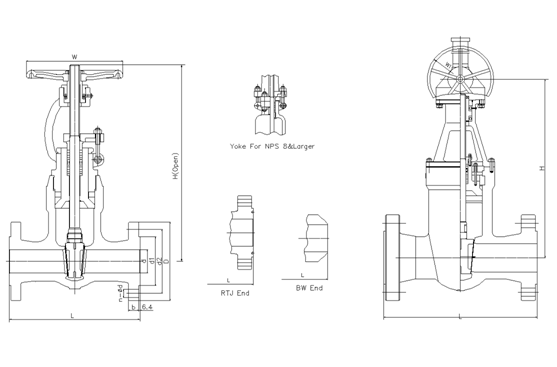
| NPS | in | 2 | 2 1/2 | 3 | 4 | 5 | 6 | 8 | 10 | 12 | 14 | 16 |
| d | mm | 47 | 57 | 70 | 92 | 111 | 136 | 178 | 222 | 263 | 289 | 330 |
| L(RF) | mm | 368 | 419 | 470 | 546 | 673 | 705 | 832 | 991 | 1130 | 1257 | 1384 |
| L(BW) | mm | 368 | 419 | 470 | 546 | 673 | 705 | 832 | 991 | 1130 | 1257 | 1384 |
| L(RTJ) | mm | 371 | 422 | 473 | 549 | 676 | 711 | 841 | 1000 | 1146 | 1276 | 1407 |
| d1 | mm | 92 | 105 | 127 | 157 | 186 | 216 | 270 | 324 | 381 | 413 | 470 |
| d2 | mm | 165 | 190.5 | 203.2 | 241.3 | 292.1 | 317.5 | 393.7 | 482.6 | 571.5 | 635 | 704.8 |
| D | mm | 216 | 244 | 267 | 311 | 375 | 394 | 483 | 585 | 675 | 750 | 825 |
| b | mm | 38.5 | 41.5 | 48 | 54 | 73.5 | 83 | 92.9 | 108 | 124 | 133.5 | 146.5 |
| n-Фd | mm | 8-26 | 8-29 | 8-32 | 8-35 | 8-42 | 12-39 | 12-45 | 12-51 | 16-54 | 16-61 | 16-67 |
| H | mm | 510 | 560 | 620 | 728 | 870 | 1000 | 1130 | 1360 | |||
| H1 | mm | 670 | 770 | 920 | 1070 | 1180 | 1410 | 1620 | 2020 | 2180 | ||
| W | mm | 280 | 300 | 350 | 400 | 450 | 500 | 750 | 900 | |||
| W1 | mm | 310 | 310 | 310 | 460 | 460 | 600 | 600 | 600 | 600 |
Class2500 Big Size Gate Valve
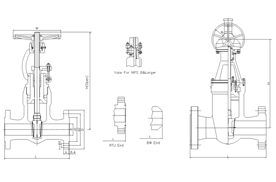
| NPS | in | 2 | 2 1/2 | 3 | 4 | 5 | 6 | 8 | 10 | 12 |
| d | mm | 38 | 47 | 57 | 73 | 92 | 111 | 146 | 184 | 219 |
| L(RF) | mm | 451 | 508 | 578 | 673 | 794 | 914 | 1022 | 1270 | 1422 |
| L(BW) | mm | 451 | 508 | 578 | 673 | 794 | 914 | 1022 | 1270 | 1422 |
| L(RTJ) | mm | 454 | 514 | 584 | 683 | 807 | 927 | 1038 | 1292 | 1445 |
| d1 | mm | 92 | 105 | 127 | 157 | 186 | 216 | 270 | 324 | 381 |
| d2 | mm | 171.4 | 196.8 | 228.6 | 273 | 323.8 | 368.3 | 438.1 | 539.7 | 619.1 |
| D | mm | 235 | 267 | 305 | 356 | 419 | 483 | 550 | 675 | 760 |
| b | mm | 51 | 57.5 | 67 | 76.5 | 92.5 | 108 | 127 | 165.5 | 184.5 |
| n-Фd | mm | 8-29 | 8-32 | 8-35 | 8-42 | 8-48 | 8-54 | 12-54 | 12-67 | 12-74 |
| H | mm | 530 | 580 | 650 | 750 | 900 | 1040 | 1150 | 1400 | |
| H1 | mm | 580 | 630 | 700 | 800 | 960 | 1100 | 1200 | 1460 | 1660 |
| W | mm | 280 | 300 | 350 | 400 | 500 | 600 | 750 | 900 | |
| W1 | mm | 310 | 310 | 310 | 310 | 460 | 460 | 460 | 600 | 600 |
API Trim NO. Table
|
No |
Seat |
Gate、disc 、ball or body |
Stem |
No |
Seat |
Gate、disc 、ball or body |
Stem | |
| 01 | 13Cr | 13Cr | 13Cr | 31 | STELLITE | 321SS | 321SS | |
| 02 | 304SS | 304SS | 304SS | 32 | STELLITE | STELLITE | 321SS | |
| 03 | 310SS | 310SS | 310SS | 33 | 347SS | 347SS | 347SS | |
| 04 | HARD 13Cr | HARD 13Cr | 13Cr | 34 | STELLITE | 347SS | 347SS | |
| 05 | STELLITE | STELLITE | 13Cr | 35 | NICKEL ALLOY | 13Cr | 13Cr | |
| 06 | Cu-Ni | 13Cr | 13Cr | 36 | A105/PTFE | A105+ENP | A105+ENP | |
| 07 | 13Cr | HARD 13Cr | 13Cr | 37 | A105/PTFE | WCB+ENP | A105+ENP | |
| 08 | STELLITE | 13Cr | 13Cr | 38 | 13Cr/PTFE | 13Cr | 13Cr | |
| 09 | Cu-Ni | Cu-Ni | Cu-Ni | 39 | 304SS/PTFE | 304SS | 304SS | |
| 10 | 316SS | 316SS | 316SS | 40 | 316SS/PTFE | 316SS | 316SS | |
| 11 | Cu-Ni | STELLITE | Cu-Ni | 41 | A105/RPTFE | A105+ENP | A105+ENP | |
| 12 | STELLITE | 316SS | 316SS | 42 | A105/RPTFE | WCB+ENP | A105+ENP | |
| 13 | ALLOY 20 | ALLOY 20 | ALLOY 20 | 43 | 13Cr/RPTFE | 13Cr | 13Cr | |
| 14 | STELLITE | ALLOY 20 | ALLOY 20 | 44 | 304SS/RPTFE | 304SS | 304SS | |
| 15 | STELLITE | STELLITE | 304SS | 45 | 316SS/RPTFE | 316SS | 316SS | |
| 16 | STELLITE | STELLITE | 316SS | 46 | A105/NYLON | A105+ENP | A105+ENP | |
| 17 | STELLITE | STELLITE | 347SS | 47 | A105/NYLON | WCB+ENP | A105+ENP | |
| 18 | STELLITE | STELLITE | ALLOY 20 | 48 | A105/NYLON | 304SS | 304SS | |
| 19 | MONEL | MONEL | MONEL | 49 | A105/NYLON | 316SS | 316SS | |
| 20 | BRONZE | BRONZE | 13Cr | 50 | 13Cr/NYLON | 13Cr | 13Cr | |
| 21 | HASTELLOY B | HASTELLOY B | HASTELLOY B | 51 | 304SS/NYLON | 304SS | 304SS | |
| 22 |
| HASTELLOY C | HASTELLOY C | 52 | 316SS/NYLON | 316SS | 316SS | |
| 23 | STELLITE | 304SS | 304SS | 53 | A105/PEEK | A105+ENP | A105+ENP | |
| 24 | 304LSS | 304LSS | 304LSS | 54 | A105/PEEK | WCB+ENP | A105+ENP | |
| 25 | STELLITE | 304LSS | 304LSS | 55 | 13Cr/PEEK | 13Cr | 13Cr | |
| 26 | STELLITE | STELLITE | 304LSS | 56 | 304SS/PEEK | 304SS | 304SS | |
| 27 | 316LSS | 316LSS | 316LSS | 57 | 316SS/PEEK | 316SS | 316SS | |
| 28 | STELLITE | 316LSS | 316LSS |
|
|
|
|
|
| 29 | STELLITE | STELLITE | 316LSS |
|
|
| ||
| 30 | 321SS | 321SS | 321SS |
|
|
|
| |
Note:please indicate it directly in the
order for the internal part’smaterial uncovered in the table

 Optimized by Seraphinite Accelerator