



 Skip to content

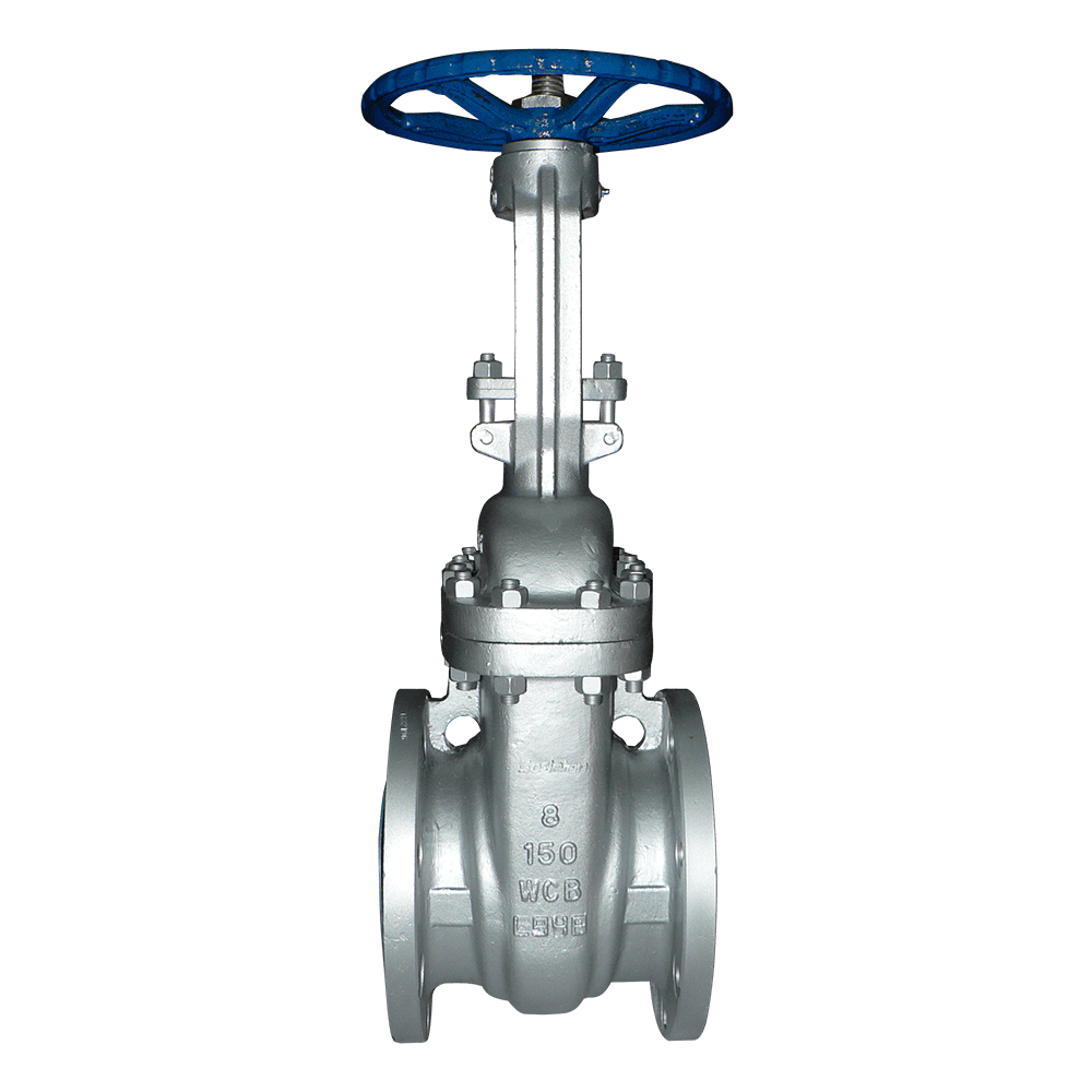
The gate is a vertically moving wedge-shaped plate. During opening, the entire gate is lifted into the bonnet area and completely removed from the flow path, allowing the medium to pass through in a straight line with minimal pressure loss compared with commonly used valve types. The drawback is that when the gate remains in an intermediate position, the medium flows at high velocity across the portion of the sealing surface that has not yet cleared the flow path. A gate valve operated in a partially open position for extended periods will therefore develop erosion grooves on the sealing surfaces and eventually fail to shut off tightly. Gate valves are consequently intended only for fully open or fully closed service. Where flow regulation is required, a globe valve or a valve specifically designed for throttling should be selected.
American standard gate valves are designed in accordance with API 600 and may use resilient or rigid wedge gates. The stem is an OS&Y design, and the exposed stem length changes with the valve stroke, allowing operators to determine the valve position at a glance. API 600 covers Class 150 through Class 2500. Pressure-temperature ratings vary with material and temperature, and the allowable pressure at elevated temperature is significantly lower than at ambient temperature for the same Class rating. Valve selection must therefore be based on the actual operating temperature and the applicable pressure-temperature rating, rather than the ambient-temperature value alone.
Body materials are selected according to the service medium and temperature: WCB for ambient-temperature oil products and water; WC6 and WC9 for high-temperature steam; CF8, CF8M, CF3, CF3M, and CN7M for corrosive services; LC1, LC2, LC3, LCB, and LCC for low-temperature service; and Monel or C95800 for seawater and chloride-containing media. Because the stem of an OS&Y gate valve is exposed to the environment, the valve should be installed with the stem pointing upward or sideways to prevent water or liquid from accumulating on the stem threads and causing corrosion. Each valve is factory tested for shell strength and sealing performance in accordance with API 598.
Main isolation lines for oil products and steam networks in refineries and chemical plants: low flow resistance and low pressure drop when fully open.
Gathering and transmission pipeline station isolation for natural gas: Class 300–900, with an exposed stem for easy visual inspection.
Boiler feedwater, condensate, and steam pipelines in power plants: WC6 and WC9 for high-temperature steam service.
Municipal and industrial water mains: the fully open gate completely clears the flow path without restricting flow capacity.
Inlet and outlet piping for low-temperature storage tanks: LC-series, LCB, and LCC bodies provide resistance to low-temperature embrittlement.
Seawater and chloride-containing service: Monel or C95800 trim for corrosion resistance.
Isolation between crude oil transmission pipeline stations: large-bore design with low pressure drop.
Service requirement: Select a gate valve for fully open/fully closed isolation service. Where flow regulation is required, select a globe valve or control valve instead. Gate valves must not be operated in a partially open position for extended periods.
Pressure-temperature rating: Refer to the applicable API 600 pressure-temperature rating for the actual operating temperature. Do not select the Class rating based solely on the allowable pressure at ambient temperature.
Materials: Use WCB for ambient-temperature oil products and water; WC6 and WC9 for high-temperature steam; CF8M and CN7M for corrosive services; LC-series materials, LCB, and LCC for low-temperature service; and Monel or C95800 for seawater.
End connections and installation: Use RF flanged ends where frequent removal is required; use butt-weld ends where flanged connections are not permitted. Install OS&Y stems upward or sideways, and fit a stem protection cover for outdoor installations.
Operation: For NPS 8 and above or Class 600 and above, a gearbox or electric actuator is recommended to avoid excessive manual operating torque.
The crude oil and desalinated water pipelines at the ANK Bashneft PAO refinery in Russia operate at Class 300 and temperatures up to 180 °C. The pipelines convey crude oil containing 2.2% sulfur and chloride ions. The original gate valves developed leakage at the bonnet connection within 16 months, and maintenance required cutting the pipeline, resulting in three days of unit downtime for each intervention and high maintenance costs.
Flowork supplied 72 NPS 4–16, Class 300 flanged gate valves featuring A216 WCB bodies, OS&Y resilient wedge gates, Stellite 6 hardfaced sealing surfaces, and RF flanged ends machined in accordance with ASME B16.5. The valves were designed in accordance with API 600 and tested for shell integrity and sealing performance in accordance with API 598, with on-site witnessing by the ANK Bashneft technical inspection department.
Since entering service in June 2022, the valves have operated continuously for three years with no bonnet or seat leakage. The replacement time per valve has been reduced from three days to five hours, and annual maintenance costs have decreased by 37%.
Q1: Why does the valve still leak internally even after the handwheel has been fully closed?
A: This is usually caused by debris trapped between the sealing surfaces or erosion of the sealing surfaces. Fully open the valve to flush the flow path and then close it again. If leakage persists, depressurize the line and inspect the sealing surfaces.
Q2: What should I do if a valve that has not been operated for a long time cannot be opened?
A: The stem threads may be dry or the sealing surfaces may have become fouled. Apply lubricant and work the valve back and forth in small increments. Do not use an extension bar to force the handwheel.
Q3: Can leakage from the packing area be addressed while the line is pressurized?
A: Yes. Evenly tighten the packing gland nuts. Do not tighten them fully in a single operation. If leakage continues, the packing should be removed and replaced.
Q4: How should rust on the stem threads of an outdoor valve be treated?
A: Remove the rust, apply lubricant, and work the stem back and forth in small increments. If corrosion is severe or the stem has been bent, depressurize the line and replace the stem.
Class150 Flanged Gate Valve

| NPS | in | 2 | 2 1/2 | 3 | 4 | 5 | 6 | 8 | 10 | 12 | 14 | 16 | 18 | 20 | 24 |
| d | mm | 51 | 64 | 76 | 102 | 127 | 152 | 203 | 254 | 305 | 337 | 387 | 438 | 489 | 591 |
| L(RF) | mm | 178 | 190 | 203 | 229 | 254 | 267 | 292 | 330 | 356 | 381 | 406 | 432 | 457 | 508 |
| L(BW) | mm | 216 | 241 | 283 | 305 | 381 | 403 | 419 | 457 | 502 | 572 | 610 | 660 | 711 | 813 |
| L(RTJ) | mm | 191 | 203 | 216 | 241 | 267 | 279 | 305 | 343 | 368 | 394 | 419 | 445 | 470 | 521 |
| d1 | mm | 92 | 105 | 127 | 157 | 186 | 216 | 270 | 324 | 381 | 413 | 470 | 533 | 584 | 692 |
| d2 | mm | 120.5 | 139.5 | 152.5 | 190.5 | 216 | 241.5 | 298.5 | 362 | 432 | 476 | 540 | 578 | 635 | 749.5 |
| D | mm | 152 | 178 | 190 | 229 | 254 | 279 | 343 | 406 | 483 | 533 | 597 | 635 | 699 | 813 |
| b | mm | 16 | 18 | 19 | 24 | 24 | 26 | 29 | 31 | 32 | 35 | 37 | 40 | 43 | 48 |
| n-Фd | mm | 4-19 | 4-19 | 4-19 | 8-19 | 8-22 | 8-22 | 8-22 | 12-25 | 12-25 | 12-29 | 16-29 | 16-32 | 20-32 | 20-35 |
| H | mm | 400 | 435 | 515 | 595 | 725 | 780 | 975 | 1150 | 1380 | 1545 | 1733 | 1915 | 2122 | 2520 |
| H1 | mm |
|
|
|
|
| 820 | 1020 | 1200 | 1430 | 1580 | 1780 | 1990 | 2220 | 2600 |
| W | mm | 200 | 200 | 250 | 280 | 280 | 300 | 350 | 400 | 450 | 500 | 500 | 500 | 600 | 600 |
| W1 | mm |
|
|
|
|
| 310 | 310 | 310 | 310 | 310 | 460 | 460 | 460 | 460 |
Class300 Flanged Gate Valve

| NPS | in | 2 | 2 1/2 | 3 | 4 | 5 | 6 | 8 | 10 | 12 | 14 | 16 | 18 | 20 | 24 |
| d | mm | 51 | 64 | 76 | 102 | 127 | 152 | 203 | 254 | 305 | 337 | 387 | 432 | 483 | 584 |
| L(RF) | mm | 216 | 241 | 283 | 305 | 381 | 403 | 419 | 457 | 502 | 762 | 838 | 914 | 991 | 1143 |
| L(BW) | mm | 216 | 241 | 283 | 305 | 381 | 403 | 419 | 457 | 502 | 762 | 838 | 914 | 991 | 1143 |
| L(RTJ) | mm | 232 | 257 | 298 | 321 | 397 | 419 | 435 | 473 | 518 | 778 | 854 | 930 | 1010 | 1165 |
| d1 | mm | 92 | 105 | 127 | 157 | 186 | 216 | 270 | 324 | 381 | 413 | 470 | 533 | 584 | 692 |
| d2 | mm | 127 | 149 | 168.5 | 200 | 235 | 270 | 330 | 387.5 | 451 | 514.5 | 571.5 | 628.5 | 686 | 813 |
| D | mm | 165 | 190 | 210 | 254 | 279 | 318 | 381 | 445 | 521 | 584 | 648 | 711 | 775 | 914 |
| b | mm | 23 | 26 | 29 | 32 | 35 | 37 | 42 | 48 | 51 | 54 | 58 | 61 | 64 | 70 |
| n-Фd | mm | 8-19 | 8-22 | 8-22 | 8-22 | 8-22 | 12-22 | 12-25 | 16-29 | 16-32 | 20-32 | 20-35 | 24-35 | 24-35 | 24-41 |
| H | mm | 420 | 446 | 537 | 619 | 722 | 806 | 1000 | 1240 | 1425 | 1585 | 1790 | 1960 | 2158 | 2576 |
| H1 | mm |
|
|
| 650 | 750 | 835 | 1030 | 1280 | 1460 | 1620 | 1830 | 2000 | 2220 | 2620 |
| W | mm | 200 | 200 | 250 | 280 | 300 | 350 | 400 | 450 | 500 | 500 | 600 | 650 | 750 | 900 |
| W1 | mm |
|
|
| 310 | 310 | 310 | 310 | 310 | 310 | 460 | 460 | 460 | 460 | 600 |
Class600 Flanged Gate Valve

| NPS | in | 2 | 2 1/2 | 3 | 4 | 5 | 6 | 8 | 10 | 12 | 14 | 16 | 18 | 20 | 24 |
| d | mm | 51 | 64 | 76 | 102 | 127 | 152 | 200 | 248 | 298 | 327 | 375 | 419 | 464 | 559 |
| L(RF) | mm | 292 | 330 | 356 | 432 | 508 | 559 | 660 | 787 | 838 | 889 | 991 | 1092 | 1194 | 1397 |
| L(BW) | mm | 292 | 330 | 356 | 432 | 508 | 559 | 660 | 787 | 838 | 889 | 991 | 1092 | 1194 | 1397 |
| L(RTJ) | mm | 295 | 333 | 359 | 435 | 511 | 562 | 664 | 791 | 841 | 892 | 994 | 1095 | 1200 | 1407 |
| d1 | mm | 92 | 105 | 127 | 157 | 186 | 216 | 270 | 324 | 381 | 413 | 470 | 533 | 584 | 692 |
| d2 | mm | 127 | 149 | 168.5 | 216 | 267 | 292 | 349 | 432 | 489 | 527 | 603 | 654 | 724 | 838 |
| D | mm | 165 | 190 | 210 | 273 | 330 | 356 | 419 | 508 | 559 | 603 | 686 | 743 | 813 | 940 |
| b | mm | 26 | 29 | 32 | 38 | 45 | 48 | 56 | 64 | 67 | 70 | 77 | 83 | 89 | 102 |
| n-Фd | mm | 8-19 | 8-22 | 8-22 | 8-25 | 8-29 | 12-29 | 12-32 | 16-35 | 20-35 | 20-38 | 20-41 | 20-44 | 24-44 | 24-52 |
| H | mm | 444 | 500 | 558 | 665 | 760 | 868 | 1073 | 1263 | 1600 | 1705 | 1835 |
|
|
|
| H1 | mm |
|
| 585 | 695 | 790 | 900 | 1110 | 1300 | 1650 | 1750 | 1900 | 2020 | 2172 | 2650 |
| W | mm | 200 | 250 | 280 | 300 | 350 | 450 | 500 | 650 | 700 | 900 | 900 |
|
|
|
| W1 | mm |
|
| 310 | 310 | 310 | 310 | 310 | 460 | 460 | 460 | 460 | 600 | 600 | 600 |
Class900 Flanged Gate Valve

| NPS | in | 2 | 2 1/2 | 3 | 4 | 5 | 6 | 8 | 10 | 12 | 14 | 16 | 18 | 20 | 24 |
| d | mm | 47 | 57 | 73 | 98 | 121 | 146 | 190 | 234 | 282 | 311 | 354 | 400 | 444 | 533 |
| L(RF) | mm | 368 | 419 | 381 | 457 | 559 | 610 | 737 | 838 | 965 | 1029 | 1130 | 1219 | 1321 | 1549 |
| L(BW) | mm | 368 | 419 | 381 | 457 | 559 | 610 | 737 | 838 | 965 | 1029 | 1130 | 1219 | 1321 | 1549 |
| L(RTJ) | mm | 371 | 422 | 384 | 460 | 562 | 613 | 740 | 841 | 968 | 1039 | 1140 | 1232 | 1334 | 1568 |
| d1 | mm | 92 | 105 | 127 | 157 | 186 | 216 | 270 | 324 | 381 | 413 | 470 | 533 | 584 | 692 |
| d2 | mm | 165 | 190.5 | 190.5 | 235 | 279.4 | 317.5 | 393.7 | 469.9 | 533.4 | 558.8 | 615.9 | 685.8 | 749.3 | 901.7 |
| D | mm | 216 | 244 | 241 | 292 | 349 | 381 | 470 | 545 | 610 | 640 | 705 | 785 | 855 | 1040 |
| b | mm | 38.5 | 41.5 | 38.5 | 44.5 | 51 | 56 | 64 | 70 | 79.5 | 86 | 89 | 102 | 108 | 140 |
| n-Фd | mm | 8-26 | 8-29 | 8-26 | 8-32 | 8-35 | 12-32 | 12-39 | 16-39 | 20-39 | 20-42 | 20-45 | 20-51 | 20-54 | 20-67 |
| H | mm | 500 | 550 | 610 | 702 | 850 | 980 | 1100 | 1320 | 1500 | 1900 | 2050 |
|
|
|
| H1 | mm |
|
| 660 | 750 | 900 | 1060 | 1140 | 1370 | 1560 | 1950 | 2100 | 2300 | 2450 | 2600 |
| W | mm | 280 | 280 | 300 | 350 | 400 | 500 | 650 | 700 | 900 | 900 | 900 |
|
|
|
| W1 | mm |
|
| 310 | 310 | 310 | 460 | 460 | 460 | 460 | 600 | 600 | 600 | 600 | 600 |
Class1500 Flanged Gate Valve

| NPS | in | 2 | 2 1/2 | 3 | 4 | 5 | 6 | 8 | 10 | 12 | 14 | 16 |
| d | mm | 47 | 57 | 70 | 92 | 111 | 136 | 178 | 222 | 263 | 289 | 330 |
| L(RF) | mm | 368 | 419 | 470 | 546 | 673 | 705 | 832 | 991 | 1130 | 1257 | 1384 |
| L(BW) | mm | 368 | 419 | 470 | 546 | 673 | 705 | 832 | 991 | 1130 | 1257 | 1384 |
| L(RTJ) | mm | 371 | 422 | 473 | 549 | 676 | 711 | 841 | 1000 | 1146 | 1276 | 1407 |
| d1 | mm | 92 | 105 | 127 | 157 | 186 | 216 | 270 | 324 | 381 | 413 | 470 |
| d2 | mm | 165 | 190.5 | 203.2 | 241.3 | 292.1 | 317.5 | 393.7 | 482.6 | 571.5 | 635 | 704.8 |
| D | mm | 216 | 244 | 267 | 311 | 375 | 394 | 483 | 585 | 675 | 750 | 825 |
| b | mm | 38.5 | 41.5 | 48 | 54 | 73.5 | 83 | 92.9 | 108 | 124 | 133.5 | 146.5 |
| n-Фd | mm | 8-26 | 8-29 | 8-32 | 8-35 | 8-42 | 12-39 | 12-45 | 12-51 | 16-54 | 16-61 | 16-67 |
| H | mm | 510 | 560 | 620 | 728 | 870 | 1000 | 1130 | 1360 |
|
|
|
| H1 | mm |
|
| 670 | 770 | 920 | 1070 | 1180 | 1410 | 1620 | 2020 | 2180 |
| W | mm | 280 | 300 | 350 | 400 | 450 | 500 | 750 | 900 |
|
|
|
| W1 | mm |
|
| 310 | 310 | 310 | 460 | 460 | 600 | 600 | 600 | 600 |
Class2500 Flanged Gate Valve

| NPS | in | 2 | 2 1/2 | 3 | 4 | 5 | 6 | 8 | 10 | 12 |
| d | mm | 38 | 47 | 57 | 73 | 92 | 111 | 146 | 184 | 219 |
| L(RF) | mm | 451 | 508 | 578 | 673 | 794 | 914 | 1022 | 1270 | 1422 |
| L(BW) | mm | 451 | 508 | 578 | 673 | 794 | 914 | 1022 | 1270 | 1422 |
| L(RTJ) | mm | 454 | 514 | 584 | 683 | 807 | 927 | 1038 | 1292 | 1445 |
| d1 | mm | 92 | 105 | 127 | 157 | 186 | 216 | 270 | 324 | 381 |
| d2 | mm | 171.4 | 196.8 | 228.6 | 273 | 323.8 | 368.3 | 438.1 | 539.7 | 619.1 |
| D | mm | 235 | 267 | 305 | 356 | 419 | 483 | 550 | 675 | 760 |
| b | mm | 51 | 57.5 | 67 | 76.5 | 92.5 | 108 | 127 | 165.5 | 184.5 |
| n-Фd | mm | 8-29 | 8-32 | 8-35 | 8-42 | 8-48 | 8-54 | 12-54 | 12-67 | 12-74 |
| H | mm | 530 | 580 | 650 | 750 | 900 | 1040 | 1150 | 1400 |
|
| H1 | mm | 580 | 630 | 700 | 800 | 960 | 1100 | 1200 | 1460 | 1660 |
| W | mm | 280 | 300 | 350 | 400 | 500 | 600 | 750 | 900 |
|
| W1 | mm | 310 | 310 | 310 | 310 | 460 | 460 | 460 | 600 | 600 |
API Trim NO. Table
|
No |
Seat |
Gate、disc 、ball or body |
Stem |
No |
Seat |
Gate、disc 、ball or body |
Stem | |
| 01 | 13Cr | 13Cr | 13Cr | 31 | STELLITE | 321SS | 321SS | |
| 02 | 304SS | 304SS | 304SS | 32 | STELLITE | STELLITE | 321SS | |
| 03 | 310SS | 310SS | 310SS | 33 | 347SS | 347SS | 347SS | |
| 04 | HARD 13Cr | HARD 13Cr | 13Cr | 34 | STELLITE | 347SS | 347SS | |
| 05 | STELLITE | STELLITE | 13Cr | 35 | NICKEL ALLOY | 13Cr | 13Cr | |
| 06 | Cu-Ni | 13Cr | 13Cr | 36 | A105/PTFE | A105+ENP | A105+ENP | |
| 07 | 13Cr | HARD 13Cr | 13Cr | 37 | A105/PTFE | WCB+ENP | A105+ENP | |
| 08 | STELLITE | 13Cr | 13Cr | 38 | 13Cr/PTFE | 13Cr | 13Cr | |
| 09 | Cu-Ni | Cu-Ni | Cu-Ni | 39 | 304SS/PTFE | 304SS | 304SS | |
| 10 | 316SS | 316SS | 316SS | 40 | 316SS/PTFE | 316SS | 316SS | |
| 11 | Cu-Ni | STELLITE | Cu-Ni | 41 | A105/RPTFE | A105+ENP | A105+ENP | |
| 12 | STELLITE | 316SS | 316SS | 42 | A105/RPTFE | WCB+ENP | A105+ENP | |
| 13 | ALLOY 20 | ALLOY 20 | ALLOY 20 | 43 | 13Cr/RPTFE | 13Cr | 13Cr | |
| 14 | STELLITE | ALLOY 20 | ALLOY 20 | 44 | 304SS/RPTFE | 304SS | 304SS | |
| 15 | STELLITE | STELLITE | 304SS | 45 | 316SS/RPTFE | 316SS | 316SS | |
| 16 | STELLITE | STELLITE | 316SS | 46 | A105/NYLON | A105+ENP | A105+ENP | |
| 17 | STELLITE | STELLITE | 347SS | 47 | A105/NYLON | WCB+ENP | A105+ENP | |
| 18 | STELLITE | STELLITE | ALLOY 20 | 48 | A105/NYLON | 304SS | 304SS | |
| 19 | MONEL | MONEL | MONEL | 49 | A105/NYLON | 316SS | 316SS | |
| 20 | BRONZE | BRONZE | 13Cr | 50 | 13Cr/NYLON | 13Cr | 13Cr | |
| 21 | HASTELLOY B | HASTELLOY B | HASTELLOY B | 51 | 304SS/NYLON | 304SS | 304SS | |
| 22 |
| HASTELLOY C | HASTELLOY C | 52 | 316SS/NYLON | 316SS | 316SS | |
| 23 | STELLITE | 304SS | 304SS | 53 | A105/PEEK | A105+ENP | A105+ENP | |
| 24 | 304LSS | 304LSS | 304LSS | 54 | A105/PEEK | WCB+ENP | A105+ENP | |
| 25 | STELLITE | 304LSS | 304LSS | 55 | 13Cr/PEEK | 13Cr | 13Cr | |
| 26 | STELLITE | STELLITE | 304LSS | 56 | 304SS/PEEK | 304SS | 304SS | |
| 27 | 316LSS | 316LSS | 316LSS | 57 | 316SS/PEEK | 316SS | 316SS | |
| 28 | STELLITE | 316LSS | 316LSS |
|
|
|
|
|
| 29 | STELLITE | STELLITE | 316LSS |
|
|
| ||
| 30 | 321SS | 321SS | 321SS |
|
|
|
| |
Note:please indicate it directly in the
order for the internal part’smaterial uncovered in the table


 Optimized by Seraphinite Accelerator