



 Skip to content

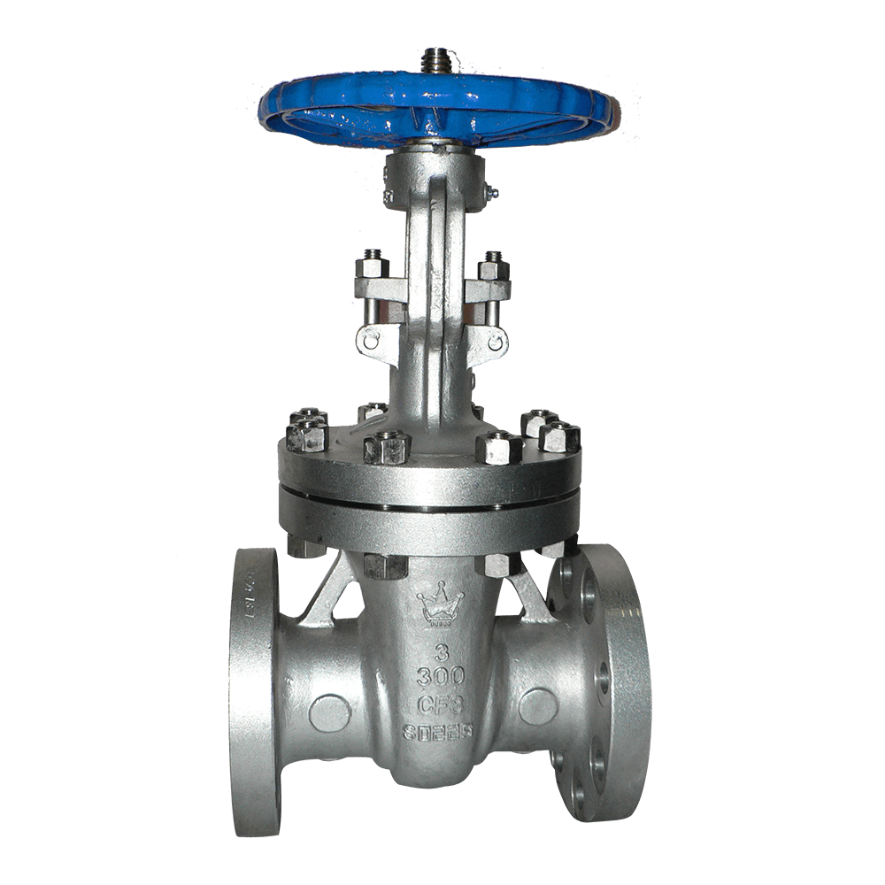
In alloy service, the gate valve is primarily used for full-open/full-closed isolation on large-diameter pipelines. The gate moves vertically along the valve seats. When fully open, the flow passage is essentially the same diameter as the pipeline, resulting in flow resistance close to that of a straight pipe and making the valve suitable for pipelines requiring pigging. The trade-off is that a gate valve is not suitable for throttling. When the gate is partially open, high-velocity flow is concentrated beneath the gate, rapidly eroding grooves into the sealing surfaces.
Wet hydrogen sulfide service is the most typical failure environment for special alloy gate valves. Hydrogen atoms generated by the dissociation of H₂S in water penetrate the steel matrix and accumulate in areas of high hardness or residual stress, resulting in sulfide stress corrosion cracking. Cracking commonly occurs in weld heat-affected zones and at bolts. Increasing wall thickness does not resolve this problem. The appropriate approach is to use sulfide-resistant alloys, control material hardness to 22 HRC or below, and perform stress-relief heat treatment on welds.
The sealing surfaces face the combined effects of solid particles and corrosion. Solid particles trapped between the gate and seat can leave indentations, after which corrosive media may penetrate through the damaged areas and propagate along grain boundaries. For this reason, sealing surfaces on special alloy gate valves are typically hardfaced with Stellite and finish-ground after hardfacing.
The stem is made from a material compatible with the valve body to minimize galvanic corrosion. The packing arrangement is selected according to the medium and temperature, using flexible graphite or braided PTFE packing. Each valve undergoes shell and seat testing in accordance with API 598. For sour service, hardness inspection and material certificates can also be provided.
Wet H₂S sour gas and amine service pipelines: sulfide-resistant material options with material hardness controlled to 22 HRC or below.
Sulfuric acid and phosphoric acid process lines: CN7M (Alloy 20) for medium- to high-temperature dilute acid service.
Hydrofluoric acid and fluoride-containing service: Monel; internal valve components must be silicon-free.
Seawater and chloride-containing cooling water systems: C95800/C95500 aluminum bronze.
Oil and gas trunklines requiring pigging: full-bore flow passage when fully open, with flow resistance close to that of a straight pipe.
Material selection: For wet H₂S and sour oil and gas service, use sulfide-resistant stainless steel or duplex stainless steel with hardness controlled to ≤22 HRC. Use CN7M for sulfuric and phosphoric acid, Monel for hydrofluoric acid with no silicon-containing materials, and C95800/C95500 for seawater service.
Service function: Gate valves are intended for full-open/full-closed isolation only and must not be used for throttling. Where flow regulation is required, a globe valve should be selected instead.
Sealing surfaces: For service containing solid particles or corrosive media, select Stellite hardfaced sealing surfaces and finish-grind them after hardfacing to prevent particle-induced indentations from developing into corrosion paths.
Stem and packing: Select a stem material compatible with the valve body to minimize galvanic corrosion. Use flexible graphite packing for high-temperature service and braided PTFE packing for corrosive media at normal temperatures. For sour service, perform pressure testing in accordance with API 598 and provide hardness inspection and material certificates.
Q: Can a gate valve be partially opened to regulate flow?A: No. When the gate is partially open, high-velocity flow is concentrated beneath the gate, eroding grooves into the sealing surfaces and causing vibration. After repeated operation, the valve may no longer provide reliable shutoff. A globe valve should be used for flow regulation.
Q: Why must material hardness be controlled in wet hydrogen sulfide service?A: Under wet conditions, H₂S promotes hydrogen penetration into the steel matrix. Areas with excessive hardness or high residual stress are more susceptible to sulfide stress corrosion cracking. Therefore, material hardness must be controlled to 22 HRC or below, together with stress-relief heat treatment.
Q: What should I do if the handwheel continues to turn after the gate valve is fully open?A: Once fully open, the gate has cleared the seats, and continued stem rotation can occur. At this point, turn the handwheel back by half a turn so that the gate is slightly seated, preventing prolonged exposure of the gate to flow-induced erosion and vibration.
At Kuwait Oil Company (KOC)’s northern oilfield, sour gas and amine service pipelines operate at Class 300 and convey wet H₂S and CO₂ at temperatures up to 130 °C. The original carbon steel gate valves failed within nine months due to sulfide stress corrosion cracking in wet H₂S service, triggering H₂S alarms and requiring repeated isolation and maintenance.
Flowork supplied 76 NPS 1–3, Class 300 special alloy gate valves featuring 316L stainless steel valve bodies and trim subjected to solution annealing, with hardness ≤22 HRC and compliance with NACE MR0175, rising-stem wedge gates, Stellite 6 hardfaced sealing surfaces, and socket-weld ends. The valves were designed in accordance with API 600 and tested in accordance with API 598, with inspection witnessed on site by the KOC Quality Control Department.
Since commissioning in May 2021, the valves have operated continuously for four years with zero leakage. H₂S alarm events decreased from five per year to zero, amine consumption was reduced by 14%, and annual plant availability increased to 99.2%.
Class150 Special Alloy Gate Valve
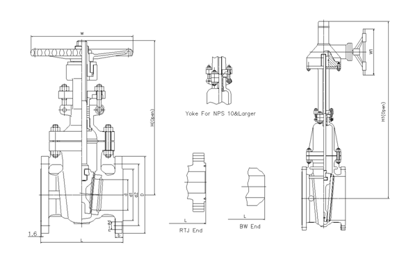
| NPS | in | 2 | 2 1/2 | 3 | 4 | 5 | 6 | 8 | 10 | 12 | 14 | 16 | 18 | 20 | 24 |
| d | mm | 51 | 64 | 76 | 102 | 127 | 152 | 203 | 254 | 305 | 337 | 387 | 438 | 489 | 591 |
| L(RF) | mm | 178 | 190 | 203 | 229 | 254 | 267 | 292 | 330 | 356 | 381 | 406 | 432 | 457 | 508 |
| L(BW) | mm | 216 | 241 | 283 | 305 | 381 | 403 | 419 | 457 | 502 | 572 | 610 | 660 | 711 | 813 |
| L(RTJ) | mm | 191 | 203 | 216 | 241 | 267 | 279 | 305 | 343 | 368 | 394 | 419 | 445 | 470 | 521 |
| d1 | mm | 92 | 105 | 127 | 157 | 186 | 216 | 270 | 324 | 381 | 413 | 470 | 533 | 584 | 692 |
| d2 | mm | 120.5 | 139.5 | 152.5 | 190.5 | 216 | 241.5 | 298.5 | 362 | 432 | 476 | 540 | 578 | 635 | 749.5 |
| D | mm | 152 | 178 | 190 | 229 | 254 | 279 | 343 | 406 | 483 | 533 | 597 | 635 | 699 | 813 |
| b | mm | 16 | 18 | 19 | 24 | 24 | 26 | 29 | 31 | 32 | 35 | 37 | 40 | 43 | 48 |
| n-Фd | mm | 4-19 | 4-19 | 4-19 | 8-19 | 8-22 | 8-22 | 8-22 | 12-25 | 12-25 | 12-29 | 16-29 | 16-32 | 20-32 | 20-35 |
| H | mm | 400 | 435 | 515 | 595 | 725 | 780 | 975 | 1150 | 1380 | 1545 | 1733 | 1915 | 2122 | 2520 |
| H1 | mm |
|
|
|
|
| 820 | 1020 | 1200 | 1430 | 1580 | 1780 | 1990 | 2220 | 2600 |
| W | mm | 200 | 200 | 250 | 280 | 280 | 300 | 350 | 400 | 450 | 500 | 500 | 500 | 600 | 600 |
| W1 | mm |
|
|
|
|
| 310 | 310 | 310 | 310 | 310 | 460 | 460 | 460 | 460 |
Class300 Special Alloy Gate Valve
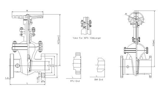
| NPS | in | 2 | 2 1/2 | 3 | 4 | 5 | 6 | 8 | 10 | 12 | 14 | 16 | 18 | 20 | 24 |
| d | mm | 51 | 64 | 76 | 102 | 127 | 152 | 203 | 254 | 305 | 337 | 387 | 432 | 483 | 584 |
| L(RF) | mm | 216 | 241 | 283 | 305 | 381 | 403 | 419 | 457 | 502 | 762 | 838 | 914 | 991 | 1143 |
| L(BW) | mm | 216 | 241 | 283 | 305 | 381 | 403 | 419 | 457 | 502 | 762 | 838 | 914 | 991 | 1143 |
| L(RTJ) | mm | 232 | 257 | 298 | 321 | 397 | 419 | 435 | 473 | 518 | 778 | 854 | 930 | 1010 | 1165 |
| d1 | mm | 92 | 105 | 127 | 157 | 186 | 216 | 270 | 324 | 381 | 413 | 470 | 533 | 584 | 692 |
| d2 | mm | 127 | 149 | 168.5 | 200 | 235 | 270 | 330 | 387.5 | 451 | 514.5 | 571.5 | 628.5 | 686 | 813 |
| D | mm | 165 | 190 | 210 | 254 | 279 | 318 | 381 | 445 | 521 | 584 | 648 | 711 | 775 | 914 |
| b | mm | 23 | 26 | 29 | 32 | 35 | 37 | 42 | 48 | 51 | 54 | 58 | 61 | 64 | 70 |
| n-Фd | mm | 8-19 | 8-22 | 8-22 | 8-22 | 8-22 | 12-22 | 12-25 | 16-29 | 16-32 | 20-32 | 20-35 | 24-35 | 24-35 | 24-41 |
| H | mm | 420 | 446 | 537 | 619 | 722 | 806 | 1000 | 1240 | 1425 | 1585 | 1790 | 1960 | 2158 | 2576 |
| H1 | mm |
|
|
| 650 | 750 | 835 | 1030 | 1280 | 1460 | 1620 | 1830 | 2000 | 2220 | 2620 |
| W | mm | 200 | 200 | 250 | 280 | 300 | 350 | 400 | 450 | 500 | 500 | 600 | 650 | 750 | 900 |
| W1 | mm |
|
|
| 310 | 310 | 310 | 310 | 310 | 310 | 460 | 460 | 460 | 460 | 600 |
Class600 Special Alloy Gate Valve
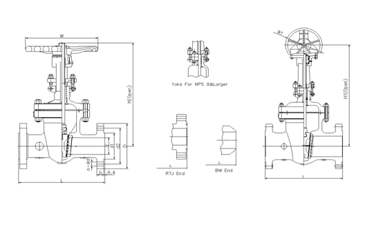
| NPS | in | 2 | 2 1/2 | 3 | 4 | 5 | 6 | 8 | 10 | 12 | 14 | 16 | 18 | 20 | 24 |
| d | mm | 51 | 64 | 76 | 102 | 127 | 152 | 200 | 248 | 298 | 327 | 375 | 419 | 464 | 559 |
| L(RF) | mm | 292 | 330 | 356 | 432 | 508 | 559 | 660 | 787 | 838 | 889 | 991 | 1092 | 1194 | 1397 |
| L(BW) | mm | 292 | 330 | 356 | 432 | 508 | 559 | 660 | 787 | 838 | 889 | 991 | 1092 | 1194 | 1397 |
| L(RTJ) | mm | 295 | 333 | 359 | 435 | 511 | 562 | 664 | 791 | 841 | 892 | 994 | 1095 | 1200 | 1407 |
| d1 | mm | 92 | 105 | 127 | 157 | 186 | 216 | 270 | 324 | 381 | 413 | 470 | 533 | 584 | 692 |
| d2 | mm | 127 | 149 | 168.5 | 216 | 267 | 292 | 349 | 432 | 489 | 527 | 603 | 654 | 724 | 838 |
| D | mm | 165 | 190 | 210 | 273 | 330 | 356 | 419 | 508 | 559 | 603 | 686 | 743 | 813 | 940 |
| b | mm | 26 | 29 | 32 | 38 | 45 | 48 | 56 | 64 | 67 | 70 | 77 | 83 | 89 | 102 |
| n-Фd | mm | 8-19 | 8-22 | 8-22 | 8-25 | 8-29 | 12-29 | 12-32 | 16-35 | 20-35 | 20-38 | 20-41 | 20-44 | 24-44 | 24-52 |
| H | mm | 444 | 500 | 558 | 665 | 760 | 868 | 1073 | 1263 | 1600 | 1705 | 1835 |
|
|
|
| H1 | mm |
|
| 585 | 695 | 790 | 900 | 1110 | 1300 | 1650 | 1750 | 1900 | 2020 | 2172 | 2650 |
| W | mm | 200 | 250 | 280 | 300 | 350 | 450 | 500 | 650 | 700 | 900 | 900 |
|
|
|
| W1 | mm |
|
| 310 | 310 | 310 | 310 | 310 | 460 | 460 | 460 | 460 | 600 | 600 | 600 |
Class900Special Alloy Gate Valve
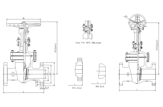
| NPS | in | 2 | 2 1/2 | 3 | 4 | 5 | 6 | 8 | 10 | 12 | 14 | 16 | 18 | 20 | 24 |
| d | mm | 47 | 57 | 73 | 98 | 121 | 146 | 190 | 234 | 282 | 311 | 354 | 400 | 444 | 533 |
| L(RF) | mm | 368 | 419 | 381 | 457 | 559 | 610 | 737 | 838 | 965 | 1029 | 1130 | 1219 | 1321 | 1549 |
| L(BW) | mm | 368 | 419 | 381 | 457 | 559 | 610 | 737 | 838 | 965 | 1029 | 1130 | 1219 | 1321 | 1549 |
| L(RTJ) | mm | 371 | 422 | 384 | 460 | 562 | 613 | 740 | 841 | 968 | 1039 | 1140 | 1232 | 1334 | 1568 |
| d1 | mm | 92 | 105 | 127 | 157 | 186 | 216 | 270 | 324 | 381 | 413 | 470 | 533 | 584 | 692 |
| d2 | mm | 165 | 190.5 | 190.5 | 235 | 279.4 | 317.5 | 393.7 | 469.9 | 533.4 | 558.8 | 615.9 | 685.8 | 749.3 | 901.7 |
| D | mm | 216 | 244 | 241 | 292 | 349 | 381 | 470 | 545 | 610 | 640 | 705 | 785 | 855 | 1040 |
| b | mm | 38.5 | 41.5 | 38.5 | 44.5 | 51 | 56 | 64 | 70 | 79.5 | 86 | 89 | 102 | 108 | 140 |
| n-Фd | mm | 8-26 | 8-29 | 8-26 | 8-32 | 8-35 | 12-32 | 12-39 | 16-39 | 20-39 | 20-42 | 20-45 | 20-51 | 20-54 | 20-67 |
| H | mm | 500 | 550 | 610 | 702 | 850 | 980 | 1100 | 1320 | 1500 | 1900 | 2050 |
|
|
|
| H1 | mm |
|
| 660 | 750 | 900 | 1060 | 1140 | 1370 | 1560 | 1950 | 2100 | 2300 | 2450 | 2600 |
| W | mm | 280 | 280 | 300 | 350 | 400 | 500 | 650 | 700 | 900 | 900 | 900 |
|
|
|
| W1 | mm |
|
| 310 | 310 | 310 | 460 | 460 | 460 | 460 | 600 | 600 | 600 | 600 | 600 |
Class1500 Special Alloy Gate Valve
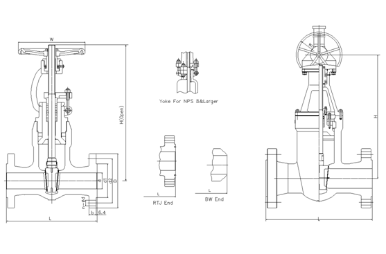
| NPS | in | 2 | 2 1/2 | 3 | 4 | 5 | 6 | 8 | 10 | 12 | 14 | 16 |
| d | mm | 47 | 57 | 70 | 92 | 111 | 136 | 178 | 222 | 263 | 289 | 330 |
| L(RF) | mm | 368 | 419 | 470 | 546 | 673 | 705 | 832 | 991 | 1130 | 1257 | 1384 |
| L(BW) | mm | 368 | 419 | 470 | 546 | 673 | 705 | 832 | 991 | 1130 | 1257 | 1384 |
| L(RTJ) | mm | 371 | 422 | 473 | 549 | 676 | 711 | 841 | 1000 | 1146 | 1276 | 1407 |
| d1 | mm | 92 | 105 | 127 | 157 | 186 | 216 | 270 | 324 | 381 | 413 | 470 |
| d2 | mm | 165 | 190.5 | 203.2 | 241.3 | 292.1 | 317.5 | 393.7 | 482.6 | 571.5 | 635 | 704.8 |
| D | mm | 216 | 244 | 267 | 311 | 375 | 394 | 483 | 585 | 675 | 750 | 825 |
| b | mm | 38.5 | 41.5 | 48 | 54 | 73.5 | 83 | 92.9 | 108 | 124 | 133.5 | 146.5 |
| n-Фd | mm | 8-26 | 8-29 | 8-32 | 8-35 | 8-42 | 12-39 | 12-45 | 12-51 | 16-54 | 16-61 | 16-67 |
| H | mm | 510 | 560 | 620 | 728 | 870 | 1000 | 1130 | 1360 |
|
|
|
| H1 | mm |
|
| 670 | 770 | 920 | 1070 | 1180 | 1410 | 1620 | 2020 | 2180 |
| W | mm | 280 | 300 | 350 | 400 | 450 | 500 | 750 | 900 |
|
|
|
| W1 | mm |
|
| 310 | 310 | 310 | 460 | 460 | 600 | 600 | 600 | 600 |
Class2500 Special Alloy Gate Valve
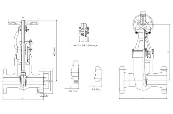
| NPS | in | 2 | 2 1/2 | 3 | 4 | 5 | 6 | 8 | 10 | 12 |
| d | mm | 38 | 47 | 57 | 73 | 92 | 111 | 146 | 184 | 219 |
| L(RF) | mm | 451 | 508 | 578 | 673 | 794 | 914 | 1022 | 1270 | 1422 |
| L(BW) | mm | 451 | 508 | 578 | 673 | 794 | 914 | 1022 | 1270 | 1422 |
| L(RTJ) | mm | 454 | 514 | 584 | 683 | 807 | 927 | 1038 | 1292 | 1445 |
| d1 | mm | 92 | 105 | 127 | 157 | 186 | 216 | 270 | 324 | 381 |
| d2 | mm | 171.4 | 196.8 | 228.6 | 273 | 323.8 | 368.3 | 438.1 | 539.7 | 619.1 |
| D | mm | 235 | 267 | 305 | 356 | 419 | 483 | 550 | 675 | 760 |
| b | mm | 51 | 57.5 | 67 | 76.5 | 92.5 | 108 | 127 | 165.5 | 184.5 |
| n-Фd | mm | 8-29 | 8-32 | 8-35 | 8-42 | 8-48 | 8-54 | 12-54 | 12-67 | 12-74 |
| H | mm | 530 | 580 | 650 | 750 | 900 | 1040 | 1150 | 1400 |
|
| H1 | mm | 580 | 630 | 700 | 800 | 960 | 1100 | 1200 | 1460 | 1660 |
| W | mm | 280 | 300 | 350 | 400 | 500 | 600 | 750 | 900 |
|
| W1 | mm | 310 | 310 | 310 | 310 | 460 | 460 | 460 | 600 | 600 |
API Trim NO. Table
|
No |
Seat |
Gate、disc 、ball or body |
Stem |
No |
Seat |
Gate、disc 、ball or body |
Stem | |
| 01 | 13Cr | 13Cr | 13Cr | 31 | STELLITE | 321SS | 321SS | |
| 02 | 304SS | 304SS | 304SS | 32 | STELLITE | STELLITE | 321SS | |
| 03 | 310SS | 310SS | 310SS | 33 | 347SS | 347SS | 347SS | |
| 04 | HARD 13Cr | HARD 13Cr | 13Cr | 34 | STELLITE | 347SS | 347SS | |
| 05 | STELLITE | STELLITE | 13Cr | 35 | NICKEL ALLOY | 13Cr | 13Cr | |
| 06 | Cu-Ni | 13Cr | 13Cr | 36 | A105/PTFE | A105+ENP | A105+ENP | |
| 07 | 13Cr | HARD 13Cr | 13Cr | 37 | A105/PTFE | WCB+ENP | A105+ENP | |
| 08 | STELLITE | 13Cr | 13Cr | 38 | 13Cr/PTFE | 13Cr | 13Cr | |
| 09 | Cu-Ni | Cu-Ni | Cu-Ni | 39 | 304SS/PTFE | 304SS | 304SS | |
| 10 | 316SS | 316SS | 316SS | 40 | 316SS/PTFE | 316SS | 316SS | |
| 11 | Cu-Ni | STELLITE | Cu-Ni | 41 | A105/RPTFE | A105+ENP | A105+ENP | |
| 12 | STELLITE | 316SS | 316SS | 42 | A105/RPTFE | WCB+ENP | A105+ENP | |
| 13 | ALLOY 20 | ALLOY 20 | ALLOY 20 | 43 | 13Cr/RPTFE | 13Cr | 13Cr | |
| 14 | STELLITE | ALLOY 20 | ALLOY 20 | 44 | 304SS/RPTFE | 304SS | 304SS | |
| 15 | STELLITE | STELLITE | 304SS | 45 | 316SS/RPTFE | 316SS | 316SS | |
| 16 | STELLITE | STELLITE | 316SS | 46 | A105/NYLON | A105+ENP | A105+ENP | |
| 17 | STELLITE | STELLITE | 347SS | 47 | A105/NYLON | WCB+ENP | A105+ENP | |
| 18 | STELLITE | STELLITE | ALLOY 20 | 48 | A105/NYLON | 304SS | 304SS | |
| 19 | MONEL | MONEL | MONEL | 49 | A105/NYLON | 316SS | 316SS | |
| 20 | BRONZE | BRONZE | 13Cr | 50 | 13Cr/NYLON | 13Cr | 13Cr | |
| 21 | HASTELLOY B | HASTELLOY B | HASTELLOY B | 51 | 304SS/NYLON | 304SS | 304SS | |
| 22 |
| HASTELLOY C | HASTELLOY C | 52 | 316SS/NYLON | 316SS | 316SS | |
| 23 | STELLITE | 304SS | 304SS | 53 | A105/PEEK | A105+ENP | A105+ENP | |
| 24 | 304LSS | 304LSS | 304LSS | 54 | A105/PEEK | WCB+ENP | A105+ENP | |
| 25 | STELLITE | 304LSS | 304LSS | 55 | 13Cr/PEEK | 13Cr | 13Cr | |
| 26 | STELLITE | STELLITE | 304LSS | 56 | 304SS/PEEK | 304SS | 304SS | |
| 27 | 316LSS | 316LSS | 316LSS | 57 | 316SS/PEEK | 316SS | 316SS | |
| 28 | STELLITE | 316LSS | 316LSS |
|
|
|
|
|
| 29 | STELLITE | STELLITE | 316LSS |
|
|
| ||
| 30 | 321SS | 321SS | 321SS |
|
|
|
| |
Note:please indicate it directly in the
order for the internal part’smaterial uncovered in the table
 Optimized by Seraphinite Accelerator